
Installation Guide
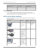
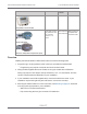
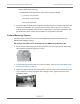


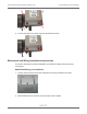
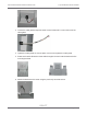
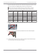
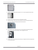
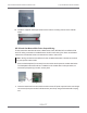
Table Of Contents
- Cellular 500G Module Remote Mount Installation Guide
- Contents
- New in This Document
- 1 Introduction
- 2 Mounting
- 3 Programming
- 4 Specific Meter Manufacturer Installation
- 5 Using Gel-cap Connectors to Complete Wiring Connections
- 6 Optional Sealant Application Instructions
- A Important Safety and Compliance Information
- U.S. and Canadian Patent Numbers
- USA, FCC Part 15 Spectrum Compliance
- Modifications, Repairs, Installation, and Removal
- Canada, ISED Spectrum Compliance
- RF Exposure (FCC/ISED)
- Transportation Classification
- Lithium Battery Safety
- Equipment Repairs
- Intrinsic Safety
- Electrostatic Ignition Hazard
- Module Cleaning
- Do Not Drop

7. Splice the meter pulse output wires to the module wires using gel cap connectors. Follow
the wire connections for the D800/D1000 to module wire connections below.
Note: Use a crimping tool compatible with gel-connectors. Details on using the
crimping tool are included in the mounting installation section of this document.
D800/D1000 meter Module
Pulse output Wire Pulse output 1 Pulse output 2 Pulse output 1
with fault
Pulse output 2
with fault
Output 1+ Brown White and blue White
Output 1- Green Red Red
Output 2+ White White and blue White
Output 2- Black Red Red
Output 3+ Red White White
Output 3- Blue Blue Blue
8. Install a cable tie strain relief on the cable approximately 1/8 inch from the end of the cable
insulation.
9. Position the cable so the strain relief is just inside the slot on the module’s backplate.
10. Carefully fold the module wires into the module’s housing. Do not pinch the wires of gel
connections between the housing and the backplate.
Cellular 500G Module Remote Mount Installation Guide 4 Specific Meter Manufacturer Installation
October 11, 2021 815-0622-00 REV 000 Itron, Inc. Page 58 of 99
DRAFT