
Installation Guide
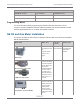
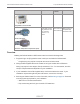
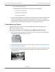


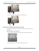
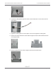
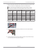
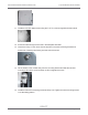
Table Of Contents
- Cellular 500G Module Remote Mount Installation Guide
- Contents
- New in This Document
- 1 Introduction
- 2 Mounting
- 3 Programming
- 4 Specific Meter Manufacturer Installation
- 5 Using Gel-cap Connectors to Complete Wiring Connections
- 6 Optional Sealant Application Instructions
- A Important Safety and Compliance Information
- U.S. and Canadian Patent Numbers
- USA, FCC Part 15 Spectrum Compliance
- Modifications, Repairs, Installation, and Removal
- Canada, ISED Spectrum Compliance
- RF Exposure (FCC/ISED)
- Transportation Classification
- Lithium Battery Safety
- Equipment Repairs
- Intrinsic Safety
- Electrostatic Ignition Hazard
- Module Cleaning
- Do Not Drop

11. Install the four back plate screws using the T-15 Torx screws supplied with the module.
12. Route the cable through the channel in the backplate standoffs.
13. Insert the 8-32 by 1/2 inch screw into the top hole in the meter mounting bracket and
thread one of the Kep nuts loosely onto the end of the screw.
14. Tilt the bottom of the module away from the mounting bracket and slide the notched
mounting hub onto the screw and Kep nut. Do not tighten the screw.
15. Install the bottom two mounting screws and Kep nuts. Tighten the three mounting screws
in an alternating pattern.
Cellular 500G Module Remote Mount Installation Guide 4 Specific Meter Manufacturer Installation
October 11, 2021 815-0622-00 REV 000 Itron, Inc. Page 59 of 99
DRAFT