
Installation Guide
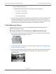


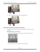
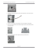
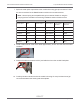
Table Of Contents
- Cellular 500G Module Remote Mount Installation Guide
- Contents
- New in This Document
- 1 Introduction
- 2 Mounting
- 3 Programming
- 4 Specific Meter Manufacturer Installation
- 5 Using Gel-cap Connectors to Complete Wiring Connections
- 6 Optional Sealant Application Instructions
- A Important Safety and Compliance Information
- U.S. and Canadian Patent Numbers
- USA, FCC Part 15 Spectrum Compliance
- Modifications, Repairs, Installation, and Removal
- Canada, ISED Spectrum Compliance
- RF Exposure (FCC/ISED)
- Transportation Classification
- Lithium Battery Safety
- Equipment Repairs
- Intrinsic Safety
- Electrostatic Ignition Hazard
- Module Cleaning
- Do Not Drop

16. Install the supplied red tamper seals over the bottom mounting screws on the Cellular
500G.
GE Oil and Gas Meters With Pulse Output Wiring
These instructions describe B3 series, LMMA series, IMC, IMC/W2, MC2, and Series ES3
and ETC wiring connections. Installations are similar in their wiring of a meter manufacturer
cable to the module that is then connected to the index or instrument.
Note: Wiring connections are different for the models as described. Use the connections
for your specific meter model.
1. Remove the backplate (four screws) from the module and expose the module lead wires.
The backplate and screws will be re-installed on the module later in this procedure, so
store them (temporarily) in a safe, secure place.
2. Insert the lead wires from the module and the correct GE pulse output wire into new 3M gel
connectors (Itron part number CON-0023-001) and crimp using a 3M hand-held crimping
tool.
Cellular 500G Module Remote Mount Installation Guide 4 Specific Meter Manufacturer Installation
October 11, 2021 815-0622-00 REV 000 Itron, Inc. Page 60 of 99
DRAFT