
Installation Guide
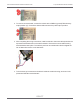

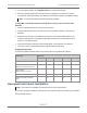
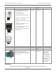
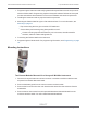

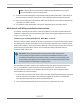

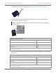
Table Of Contents
- Cellular 500G Module Remote Mount Installation Guide
- Contents
- New in This Document
- 1 Introduction
- 2 Mounting
- 3 Programming
- 4 Specific Meter Manufacturer Installation
- 5 Using Gel-cap Connectors to Complete Wiring Connections
- 6 Optional Sealant Application Instructions
- A Important Safety and Compliance Information
- U.S. and Canadian Patent Numbers
- USA, FCC Part 15 Spectrum Compliance
- Modifications, Repairs, Installation, and Removal
- Canada, ISED Spectrum Compliance
- RF Exposure (FCC/ISED)
- Transportation Classification
- Lithium Battery Safety
- Equipment Repairs
- Intrinsic Safety
- Electrostatic Ignition Hazard
- Module Cleaning
- Do Not Drop

Note: Use a crimping tool compatible with gel-connectors. For information about
crimping the connections, see Using Gel-cap Connectors to Complete Wiring
Connections on page 92. The same process is used for wiring cables to the module.
Each meter or cable may have different wire colors and wiring instructions. See the
specific wiring configuration for your product. Wiring configurations for the B3, LMMA,
IMC/W2, MC2, ES3, and ETC meters with pulse outputs are provided in the following
information.
GE supplied cable that connects to a B3, LMMA, IMC/W2, or MC2 Module
Blue Blue
White White
Red Red
Pulse output Wire Pulse output 1 only Pulse output with 1 fault
ES3 or ETC Module
Output 1+ White White and blue White
Output 1- Black Red Red
Output 3+ Red White
Output 3- Green Blue
Wiring for direct connection to the IMC/W2
1. To receive corrected reads, skip to Step 2.
To receive uncorrected reads, connect the red wire to terminal block 3 (TB3 telemetry
output) GND1 (ground) position (B). Connect the white and blue wires to the pulse output
1 position (A).
Cellular 500G Module Remote Mount Installation Guide 4 Specific Meter Manufacturer Installation
October 11, 2021 815-0622-00 REV 000 Itron, Inc. Page 61 of 99
DRAFT