
Installation Guide
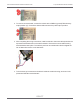

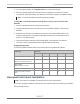
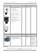
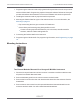

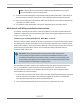

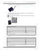
Table Of Contents
- Cellular 500G Module Remote Mount Installation Guide
- Contents
- New in This Document
- 1 Introduction
- 2 Mounting
- 3 Programming
- 4 Specific Meter Manufacturer Installation
- 5 Using Gel-cap Connectors to Complete Wiring Connections
- 6 Optional Sealant Application Instructions
- A Important Safety and Compliance Information
- U.S. and Canadian Patent Numbers
- USA, FCC Part 15 Spectrum Compliance
- Modifications, Repairs, Installation, and Removal
- Canada, ISED Spectrum Compliance
- RF Exposure (FCC/ISED)
- Transportation Classification
- Lithium Battery Safety
- Equipment Repairs
- Intrinsic Safety
- Electrostatic Ignition Hazard
- Module Cleaning
- Do Not Drop

5. Install the Cellular 500G backplate using the four screws previously removed from the
module and a Torx T-10 screwdriver.
6. Plug the cable into the pulse output of the index.
Important! Verify that the cable tie and gel connectors are inside the module
housing and that the cable extends out of the backplate slot. Torque the
backplate mounting screws 9 to 12 inch-pounds.
7. Mount the module as required for your application. Wall and pipe mount options are
described in Mounting on page 12. Additional options for GE specific mounting solutions
are described in the product specific mounting instructions in this GE Oil and Gas section.
Programming and Requirements Notes
GE MeterWare software is used to configure the module’s index settings.
Important! This information is subject to change without notice. Refer to the GE
MeterWare product documentation to verify the most current information about
programming and configuring the corrector for use with the Cellular 500G.
1. Open the GE Dresser MeterWare software to change the Cellular 500G settings.
2. Select the LiveData tab.
3. Confirm the firmware version and current index settings.
Cellular 500G Module Remote Mount Installation Guide 4 Specific Meter Manufacturer Installation
October 11, 2021 815-0622-00 REV 000 Itron, Inc. Page 63 of 99
DRAFT