
Installation Guide
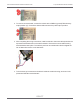

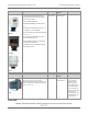
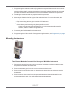


Table Of Contents
- Cellular 500G Module Remote Mount Installation Guide
- Contents
- New in This Document
- 1 Introduction
- 2 Mounting
- 3 Programming
- 4 Specific Meter Manufacturer Installation
- 5 Using Gel-cap Connectors to Complete Wiring Connections
- 6 Optional Sealant Application Instructions
- A Important Safety and Compliance Information
- U.S. and Canadian Patent Numbers
- USA, FCC Part 15 Spectrum Compliance
- Modifications, Repairs, Installation, and Removal
- Canada, ISED Spectrum Compliance
- RF Exposure (FCC/ISED)
- Transportation Classification
- Lithium Battery Safety
- Equipment Repairs
- Intrinsic Safety
- Electrostatic Ignition Hazard
- Module Cleaning
- Do Not Drop

Warning! The battery pack, main board, and switchboard may be damaged if
left in the Honeywell Instrument volume corrector while completing this
installation.
5. Drill two 3/16 inch holes in the back of the Mini-Max enclosure as specified by the
information included in the kit. Remove any metal shavings from the enclosure.
6. Clean the Cellular 500Gs with the alcohol wipe where you will place the corrected and
uncorrected labels (included in the kit).
Note: Clean the modules with the alcohol wipe to ensure good label adhesion.
7. Mount the module for corrected pulse outputs on the left bracket mounting space.
a. Insert three #8-32 by 1/2 inch screws in a triangular pattern.
Install the top screw so the head of the screw is approximately 1/8 inch from the
mounting bracket surface.
b. Slide the module onto the screw so the mounting lug fits securely onto the screw. If
necessary, remove the module and make any necessary adjustment to the screw
depth to ensure a secure fit.
c. Install the two bottom screws in an alternating fashion.
8. Mount the module for uncorrected pulse outputs on the right bracket mounting space.
a. Insert three #8-32 by 1/2 inch screws in a triangular pattern.
Install the top screw so the head of the screw is approximately 1/8 inch from the
mounting bracket surface.
b. Slide the module onto the screw so the mounting lug fits securely onto the screw. If
necessary, remove the module and make any necessary adjustment to the screw
depth to ensure a secure fit.
c. Install the two bottom screws in an alternating fashion.
9. Route the module cables under the bracket edge and toward the rear of the Honeywell
Instrument.
10. Mount the mounting bracket (Honeywell Instrument part number 22-1077, included in the
kit) onto the Mini-Max enclosure.
a. Place a #8 metal flat washer followed by a rubber sealing washer onto both #8-32 by
3/8 inch screws.
b. Align the lower threaded holes in the mounting bracket with the drilled enclosure holes
and insert a screw/washer through the enclosure housing. Screws heads must be
inside the enclosure.
c. Tighten both screws using a screwdriver.
Cellular 500G Module Remote Mount Installation Guide 4 Specific Meter Manufacturer Installation
October 11, 2021 815-0622-00 REV 000 Itron, Inc. Page 67 of 99
DRAFT