
Installation Guide
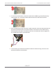

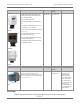
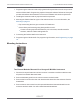


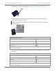
Table Of Contents
- Cellular 500G Module Remote Mount Installation Guide
- Contents
- New in This Document
- 1 Introduction
- 2 Mounting
- 3 Programming
- 4 Specific Meter Manufacturer Installation
- 5 Using Gel-cap Connectors to Complete Wiring Connections
- 6 Optional Sealant Application Instructions
- A Important Safety and Compliance Information
- U.S. and Canadian Patent Numbers
- USA, FCC Part 15 Spectrum Compliance
- Modifications, Repairs, Installation, and Removal
- Canada, ISED Spectrum Compliance
- RF Exposure (FCC/ISED)
- Transportation Classification
- Lithium Battery Safety
- Equipment Repairs
- Intrinsic Safety
- Electrostatic Ignition Hazard
- Module Cleaning
- Do Not Drop

Note: Aligning the second bracket threaded hole and drilled hole may require
some manipulation of the mounting bracket.
11. Insert the module cables (both units) through the large cable strain relief on the left rear of
the instrument’s enclosure. Leave a 1/2 to 1 inch drip loop under the cable strain relief.
12. Secure three cable ties on the module cables in three places on the cables as specified by
information included in the kit.
13. Re-install the input switchboard, main board, and battery pack removed in step 2.
Mechanical and Wiring Installation Instructions
This section includes the information to wire two modules to a single Honeywell Instrument.
Installation requires the correct programming parameters (for programming parameters, see
Programming on page 18).
Connecting to a Honeywell Mini-AT, Mini-Max, or EC-AT
With Itron Cellular 500Gs, utilities can receive corrected and uncorrected consumption values
by installing two modules. The module for corrected reads is attached to the corrector’s pulse
outputo the module for uncorrected reads is attached to the input switch board. The corrected
pulse output is programmable, and the uncorrected pulse output is dependent on the
connected meter’s drive rate.
Important! Some Honeywell Instruments have two pulse outputs so the
uncorrected pulse output could be connected to the additional output, but the
connection should be to the input switch board in case the corrector battery fails.
Counts will be collected if the uncorrected pulse is connected to the switch board
since the board is not dependent on battery power.
This installation procedure requires a Honeywell mounting kit (Honeywell part number 22-
1077). The illustrations show connection to a Honeywell Mini-AT. Connection to the
Honeywell EC-AT and Mini-AT are similar to these instructions. See Honeywell product
documentation for more information.
1. Connect the corrected module wires to TB1 on the Mini-Max board following the Corrected
module connection information. Use Honeywell upgrade kit 40-2678-1 to provide the
second pulse output channel for the uncorrected endpoint.
2. Inser. The Cellular 500G cable into the instrument’s compression connector.
Cellular 500G Module Remote Mount Installation Guide 4 Specific Meter Manufacturer Installation
October 11, 2021 815-0622-00 REV 000 Itron, Inc. Page 68 of 99
DRAFT