
Installation Guide
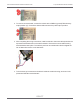

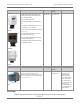
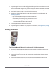


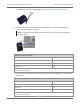
Table Of Contents
- Cellular 500G Module Remote Mount Installation Guide
- Contents
- New in This Document
- 1 Introduction
- 2 Mounting
- 3 Programming
- 4 Specific Meter Manufacturer Installation
- 5 Using Gel-cap Connectors to Complete Wiring Connections
- 6 Optional Sealant Application Instructions
- A Important Safety and Compliance Information
- U.S. and Canadian Patent Numbers
- USA, FCC Part 15 Spectrum Compliance
- Modifications, Repairs, Installation, and Removal
- Canada, ISED Spectrum Compliance
- RF Exposure (FCC/ISED)
- Transportation Classification
- Lithium Battery Safety
- Equipment Repairs
- Intrinsic Safety
- Electrostatic Ignition Hazard
- Module Cleaning
- Do Not Drop

3. Strip one inch of the outer insulation from the cable.
Warning! Keep wires away from the rotating magnetic spindle in the Honeywell
Instrument.
4. Strip 0.25 inch individual wire insulation from the red, white, and blue lead wires.
–
Count enabling wire (pulsed ground reference)
–
Count sensing wire (high impedance positive reference)
–
Cut cable sensing wire (positive return)
5. Twist the blue and white wires together and connect them to the Honeywell Instrument
terminal strip connector (Phoenix connector) following the Honeywell Instrument Item
Cellular 500G Module Remote Mount Installation Guide 4 Specific Meter Manufacturer Installation
October 11, 2021 815-0622-00 REV 000 Itron, Inc. Page 69 of 99
DRAFT