
Installation Guide
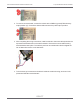

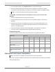
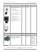

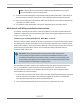

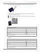
Table Of Contents
- Cellular 500G Module Remote Mount Installation Guide
- Contents
- New in This Document
- 1 Introduction
- 2 Mounting
- 3 Programming
- 4 Specific Meter Manufacturer Installation
- 5 Using Gel-cap Connectors to Complete Wiring Connections
- 6 Optional Sealant Application Instructions
- A Important Safety and Compliance Information
- U.S. and Canadian Patent Numbers
- USA, FCC Part 15 Spectrum Compliance
- Modifications, Repairs, Installation, and Removal
- Canada, ISED Spectrum Compliance
- RF Exposure (FCC/ISED)
- Transportation Classification
- Lithium Battery Safety
- Equipment Repairs
- Intrinsic Safety
- Electrostatic Ignition Hazard
- Module Cleaning
- Do Not Drop

Code Settings. For Item Code Settings, see Programming Parameters on page 75.
6. Connect the red wire following the Item Code Settings. For Item Code Settings, see
Programming Parameters on page 75.
Note: In Honeywell Instrument EC-AT correctors, the connector may be soldered to
the pulse board.
Corrected module connections
Mini-Max TB1 Module wire color
K terminal Red
Ya terminal Blue*
Ya terminal White*
*Twist the blue and white module wires together before connecting them to the Mini-Max board. Tighten the
terminal connection securely.
7. Connect the uncorrected module wires to the Input Switch Board UNC. VOL following the
table below.
Uncorrected module connections
Mini-Max input switch board unc. vol Module wire color
COM terminal Red
No terminal Blue*
No terminal White*
*Twist the blue and white module wires together before connecting them to the Mini-Max board. Tighten the
terminal connection securely.
Cellular 500G Module Remote Mount Installation Guide 4 Specific Meter Manufacturer Installation
October 11, 2021 815-0622-00 REV 000 Itron, Inc. Page 70 of 99
DRAFT