
Installation Guide
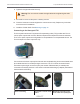
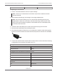
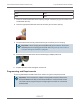
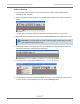
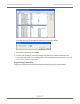
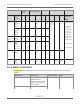
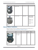
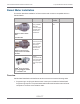
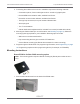
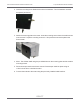
Table Of Contents
- Cellular 500G Module Remote Mount Installation Guide
- Contents
- New in This Document
- 1 Introduction
- 2 Mounting
- 3 Programming
- 4 Specific Meter Manufacturer Installation
- 5 Using Gel-cap Connectors to Complete Wiring Connections
- 6 Optional Sealant Application Instructions
- A Important Safety and Compliance Information
- U.S. and Canadian Patent Numbers
- USA, FCC Part 15 Spectrum Compliance
- Modifications, Repairs, Installation, and Removal
- Canada, ISED Spectrum Compliance
- RF Exposure (FCC/ISED)
- Transportation Classification
- Lithium Battery Safety
- Equipment Repairs
- Intrinsic Safety
- Electrostatic Ignition Hazard
- Module Cleaning
- Do Not Drop

part number 22-1929)
Completing the Connections
1. Connec. The Cellular 500G to receive TCI pulse readings.
Note: Connect one module/channel to the alarm output if the modules are used on
channels A and B.
2. Remove strain relief fitting by unscrewing it from the gray adapter plate.
Note: Do not remove the fitting’s hex nut. Unscrew the entire fitting from the gray
adapter plate. A tether line is secured to the strain relief fitting. When the strain relief
fitting is removed, the tether line pulls the unterminated wires out of the adapter plate
for access to the loose wires.
3. Loosen the strain relief fitting hex nut and remove the white plug from the center.
4. Place the strain relief fitting onto the field pulse cable.
5. If the field pulse cable is smaller than a 0.2 inch diameter, install the rubber tube supplied
with the TCI onto the cable so the strain relief will clamp onto the tube after it is reinstalled.
6. Connect the individual external pulse cable conductors to the unterminated wires following
Configuration for two modules connected to one TCI.
Configuration for two modules connected to one TCI
Channel A Module wire
Orange and brown White
Configuration for two modules connected to one TCI
Channel A Module wire
Orange and brown White
Yellow Red
Blue (alarm) Blue
Channel B
TCI Module wire
White White
Cellular 500G Module Remote Mount Installation Guide 4 Specific Meter Manufacturer Installation
October 11, 2021 815-0622-00 REV 000 Itron, Inc. Page 72 of 99
DRAFT