
Installation Guide
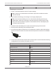
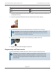
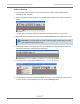
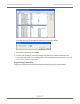
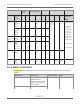
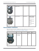
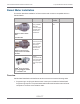
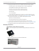
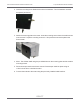
Table Of Contents
- Cellular 500G Module Remote Mount Installation Guide
- Contents
- New in This Document
- 1 Introduction
- 2 Mounting
- 3 Programming
- 4 Specific Meter Manufacturer Installation
- 5 Using Gel-cap Connectors to Complete Wiring Connections
- 6 Optional Sealant Application Instructions
- A Important Safety and Compliance Information
- U.S. and Canadian Patent Numbers
- USA, FCC Part 15 Spectrum Compliance
- Modifications, Repairs, Installation, and Removal
- Canada, ISED Spectrum Compliance
- RF Exposure (FCC/ISED)
- Transportation Classification
- Lithium Battery Safety
- Equipment Repairs
- Intrinsic Safety
- Electrostatic Ignition Hazard
- Module Cleaning
- Do Not Drop

Configuration for two modules connected to one TCI
Green Red
White Blue
7. Insert one unterminated wire into an opening of a gel-connector (six gel-connectors were
included with the TCI).
8. Insert the appropriate field cable wire into the other gel-connector opening.
9. Verify that both wires are fully inserted into the gel-connector prior to crimping.
Important! Use a crimping tool compatible with gel-connectors. Do not use
standard pliers for crimping gel-connects. See Using Gel-cap Connectors to
Complete Wiring Connections on page 92.
10. Insert the gel-connected wires into the threaded gray adapter plate hole.
11. Replace the strain relief and tighten until secure.
Programming and Requirements
The Honeywell MasterLink SQL software is used to configure Honeywell products.
Important! This information is subject to change without notice. Refer to the
Honeywell MasterLink SQL product documentation to verify the most current
information about programming and configuring the corrector for use with the
Cellular 500G.
Cellular 500G Module Remote Mount Installation Guide 4 Specific Meter Manufacturer Installation
October 11, 2021 815-0622-00 REV 000 Itron, Inc. Page 73 of 99
DRAFT