
Installation Guide
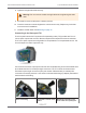
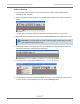
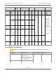
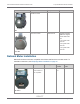
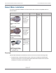
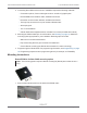
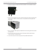
Table Of Contents
- Cellular 500G Module Remote Mount Installation Guide
- Contents
- New in This Document
- 1 Introduction
- 2 Mounting
- 3 Programming
- 4 Specific Meter Manufacturer Installation
- 5 Using Gel-cap Connectors to Complete Wiring Connections
- 6 Optional Sealant Application Instructions
- A Important Safety and Compliance Information
- U.S. and Canadian Patent Numbers
- USA, FCC Part 15 Spectrum Compliance
- Modifications, Repairs, Installation, and Removal
- Canada, ISED Spectrum Compliance
- RF Exposure (FCC/ISED)
- Transportation Classification
- Lithium Battery Safety
- Equipment Repairs
- Intrinsic Safety
- Electrostatic Ignition Hazard
- Module Cleaning
- Do Not Drop

Channel A
Corrected
Volume
Channel B
UncorrectedVolume
Channel C Pulse Output Spacing
Instrument Pulse
Output
Options
#56 #93 #57 #94 #58 #95 #115 #1014 #1015 Terminal Board
Connections /
Wiring
Wiring
ECAT Pulse
Board Ver-
2(3)
Form A
2 Cor
Vol
2 Unc
Vol
2 Cor
Vol
1=1.0
sec or
2=2.0
sec
or
4=0.5
sec
Red wire goes to
K
Blue and White
wires go to Y
Connection must
be on same
terminal board
channel (for
example, Ka/Ya;
kb/Yb; Kc/Yc)
Ka, Ya=Channel
A
Kb, Yb=Channel
B
Kc, Yc=Channel
C
Pulse
board Ver-
3(2)
FormC1
FormA
2 Cor
Vol
Mini with
Form A main
board
Main
board
Type-2*
2 Cor
Vol
Mini-AT JB29,
JB30
&JB31
Jumpered
for FormA*
2 Cor
Vol
2 Unc
Vol
Mini-Max All main
boards
2 Cor
Vol
2 Unc
Vol
1=1.0
sec
or
2=2.0
sec
TCI FormA
main
board
2 Cor
Vol
2 Cor
Vol
Itron
100G
Itron
100G
Itron Meter Installation
See for Itron meter installation information for the A-Series (1A, 305, 400, 675, and 1000)
meters.
Meter model Meter notes Itron part number Notes
1A Flat-face meter body and 1A
adapter plate have
interference fit issue causing
direct-mount solution to be
non-compatible.
ERG-7000-501
305 #2 flat-face meter
Cellular 500G Module Remote Mount Installation Guide 4 Specific Meter Manufacturer Installation
October 11, 2021 815-0622-00 REV 000 Itron, Inc. Page 76 of 99
DRAFT