
Installation Guide
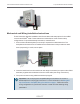
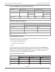
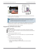
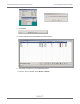
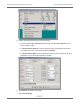

Table Of Contents
- Cellular 500G Module Remote Mount Installation Guide
- Contents
- New in This Document
- 1 Introduction
- 2 Mounting
- 3 Programming
- 4 Specific Meter Manufacturer Installation
- 5 Using Gel-cap Connectors to Complete Wiring Connections
- 6 Optional Sealant Application Instructions
- A Important Safety and Compliance Information
- U.S. and Canadian Patent Numbers
- USA, FCC Part 15 Spectrum Compliance
- Modifications, Repairs, Installation, and Removal
- Canada, ISED Spectrum Compliance
- RF Exposure (FCC/ISED)
- Transportation Classification
- Lithium Battery Safety
- Equipment Repairs
- Intrinsic Safety
- Electrostatic Ignition Hazard
- Module Cleaning
- Do Not Drop

Mechanical and Wiring Installation Instructions
These instructions describe installation with Romet cables and setup options for the AdEM
corrector and ECM2
®
meter. These instructions include the two most common setup
configurations. For specialized setup instructions, contact Romet.
1. Remove the module backplate (four screws) to expose the module lead wires. The
backplate and screws will be re-installed on the module later in this procedure so store
them (temporarily) in a safe, secure place.
2. Insert the lead wires from the module into new 3M gel connectors (Itron part number CON-
0023-001) together with the lead wire from the meter cable (see wiring connections).
3. Crimp the connectors using a 3M hand-held crimping tool.
Important! Use a crimping tool compatible with gel-connectors. Do not use a
standard pliers for crimping gel connectors. For more information, see Using Gel-
cap Connectors to Complete Wiring Connections on page 1. Follow the correct
wiring configuration for your Romet corrector or meter from the following wiring
parameters.
Cellular 500G Module Remote Mount Installation Guide 4 Specific Meter Manufacturer Installation
October 11, 2021 815-0622-00 REV 000 Itron, Inc. Page 81 of 99
DRAFT