
Installation Guide
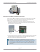
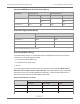
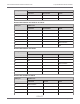
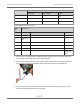
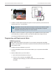

Table Of Contents
- Cellular 500G Module Remote Mount Installation Guide
- Contents
- New in This Document
- 1 Introduction
- 2 Mounting
- 3 Programming
- 4 Specific Meter Manufacturer Installation
- 5 Using Gel-cap Connectors to Complete Wiring Connections
- 6 Optional Sealant Application Instructions
- A Important Safety and Compliance Information
- U.S. and Canadian Patent Numbers
- USA, FCC Part 15 Spectrum Compliance
- Modifications, Repairs, Installation, and Removal
- Canada, ISED Spectrum Compliance
- RF Exposure (FCC/ISED)
- Transportation Classification
- Lithium Battery Safety
- Equipment Repairs
- Intrinsic Safety
- Electrostatic Ignition Hazard
- Module Cleaning
- Do Not Drop

Cable pin Module wire
Corrected Uncorrected Alarm
4 Red
5 Red
6 White and blue
Romet Cable Number 34-125-51
Cable
pin
Module wire
Correct Uncorrected Aux CC
1 Red
2 White and
blue
3 White and blue
4 Red
5 Red
6 White and
blue
4. After the wire connections are completed, install a cable tie to the meter cable just below
the exposed colored lead wires on the cable insulation.
5. Remove the excess cable tie using a hand-held side-cutter pliers. The cable tie performs
as a cable strain relief to mitigate the risk of destructive tension on the lead wires.
6. Tuck the three gel connectors and cable tie inside the module housing, as shown in the
following placement illustration and schematic.
Cellular 500G Module Remote Mount Installation Guide 4 Specific Meter Manufacturer Installation
October 11, 2021 815-0622-00 REV 000 Itron, Inc. Page 85 of 99
DRAFT