Cannon, VEAM, BIW A Historical Achievement of Technology Leadership Defining and Championing Innovation Showcasing a portfolio of creativity, ITT’s “Engineered For Life” execution embraces products which have become ubiquitous in a broad collection of markets including: Military/Aerospace, Civil Aircraft, Industrial Instrumentation, Medical, Oil & Gas, Energy, Transportation, Telecom/Handset, Computer, Consumer, and Automotive.
ITT Interconnect Solutions ITT Interconnect Solutions is a division of the multinational ITT Corporation, a $9 billion dollar global enterprise representing the brands Cannon, VEAM, and BIW. Our connector portfolio remains the most extensive in the industry offering the most reliable and cost effective range of interconnect solutions.
Interconnect Technologies & Solutions for the Transportation Industry For over 90 years, ITT has been developing innovative solutions for harsh environment applications. We have a proven track record of demonstrating our expertise and commitment to the transportation industry, offering the broadest portfolio of interconnect products.
Cannon Trident Connectors Table of Contents Description Cannon’s Trident Connector System is a versatile range of electrical connectors based on a standard contact design. These contacts are fully interchangeable throughout the Trident Connector System. The connector options include low cost retangulars, rack and panel, industrial grade circulars, harsh environment circulars and shielded circulars. Trident Connector System Connector Selection Guide . . . . . . . . . . . . . . . . . . . . . . . . . . . .
Cannon Trident Connectors Snap Together Operating Voltage1 Connector Selection Guide Flame Retardant Rack and Panel Multiway Rectangular Slimline Rectangular Up to 250 V ac rms Up to 250 V ac rms Up to 250 V ac rms * Circular Ringlock Neptune Up to 250 V ac rms Up to Up to 380 V ac 250 V ac rms rms (7 position connector only) Up to 13 A Up to 13 A Current Rating2 Up to 13 A Up to 10 A -55°C to +105°C -55°C to +105°C (-67°F to +221°F) (-67°F to +221°F) Operating (from -40°C, (from -40°C, T
Cannon Trident Connectors Snap Together - Rectangular These are low installed cost connectors rated for up to 13 A and 240 V ac. They are typically used for circuit board and internal wiring applications. Snap Together connectors facilitate easy assembly and removal of equipment such as motors, fans, transformers, etc. All Snap Together Rectangular connectors are RoHS Compliant. Applications: • Vehicle Dashboards. • Circuit board connections. • Internal connections.
Cannon Trident Connectors Snap Together - Rectangular How to Order Typical Nomenclature: TST 02 P A 0 0 * Series TST = Trident Snap Together Plating Style T = Tin Y = Gold Z = Gold Flash * = None (no contacts) Number of Contacts 02 03 04 06 12 24 36 Contact Type 0 = No Contacts (Standard for Plug and Panel Mounted Receptacle) 1 = Machined Solder Tail Pin 2 = Machined Solder Tail Socket 5 = Formed Stamped Solder Tail Pin 6 = Formed Stamped Solder Tail Socket Color of Moulding 0 = Black Type PA
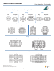
Cannon Trident Connectors Snap Together - Rectangular Contact Cavity Arrangements — Mating Face View 2-way Plug 3-way Receptacle Plug 4-way Receptacle 6-way Plug Plug Receptacle 12-way Receptacle Plug Receptacle 24-way Plug Receptacle 36-way Plug Receptacle Dimensions shown in mm (inch) Specifications and dimensions subject to change www.ittcannon.
Cannon Trident Connectors Free Plug • Accepts Pin or Socket contacts. • Contacts to be ordered separately, see page 64. • Mates with panel mounted receptacles, see page 11. • Mates with PCB mounted receptacles, see pages 12-13. Number of Contacts 2 3 4 6 12 24 36 Snap Together - Rectangular Pack of 100 Part Number Nomenclature 192990-0350 TST02PA00 192923-5920 TST03PA00 192990-0370 TST04PA00 192923-5930 TST06PA00 192923-5940 TST12PA00 192923-5950 TST24PA00 192923-5960 TST36PA00 Dimensions (max.
Cannon Trident Connectors Snap Together - Rectangular Panel Cutout Receptacle — Panel Mounted • Accepts Pin or Socket contacts. • Contacts to be ordered separately, see page 64. • Mates with Free Plugs, see page 10. • Connector Discriminating (Keying) Pins available, see page 73.
Cannon Trident Connectors Snap Together - Rectangular Figure 1 Figure 2 Receptacle — PCB Mounted for Pin Contacts • Mates with Free Plug, see page 10. • Integrally molded flanges. • Contacts are on a 5,08 (.200) grid, symmetrical on center lines. • Recommended PCB hole Ø1,15 (.045). • Connector Discriminating Caps available, see page 73.
Cannon Trident Connectors Snap Together - Rectangular Figure 1 Figure 2 Receptacle — PCB Mounted for Socket Contacts • Mates with Free Plug, see page 10. • Integrally molded flanges. • Contacts are on a 5,08 (.200) grid, symmetrical on center lines. • Recommended PCB hole Ø 1,15 (.045). • Connector Discriminating Pegs available, see page 73.
Cannon Trident Connectors Flame Retardant - Rectangular This new connector series is compliant to railway standards. The material properties are I2/F2 according to NFF16-101. These are low installed cost connectors rated for up to 13 A and 250 V ac. They are typically used for circuit board and internal wiring applications. All flame retardant connectors are RoHS Compliant. Applications: • Vehicle Dashboards. • Circuit board connections. • Internal connections. • Railway. • Lighting.
Cannon Trident Connectors Flame Retardant - Rectangular Contact Cavity Arrangements — Mating Face View 2-way 3-way 4-way 6-way Plug 12-way Receptacle Plug Receptacle 24-way Plug Receptacle 36-way Plug Receptacle Dimensions shown in mm (inch) Specifications and dimensions subject to change www.ittcannon.
Cannon Trident Connectors Free Plug • Accepts Pin or Socket contacts. • Contacts to be ordered separately, see page 64. • Mates with panel mounted receptacles, see page 17. • Connector Discriminating (Keying) Pins available, see page 73.
Cannon Trident Connectors Kit — Plug and Strain Relief Hood • Provides protection for panel mounted receptacles with pin contacts. • Shrouds can be fitted onto panels up to 1,40 (.055) thick.
Cannon Trident Connectors Snap Together - Slimline The Slimline Range offers a low profile connector system that is well suited for circuit board applications. The precision machined contacts are ideal for power and sensitive signals. All Snap Together - Slimline connectors are RoHS Compliant. Applications: • Junction Boxes. • Communications equipment. • Test equipment. • Instrumentation. Product Features • Less than 10,00 (.393) width on PC board.
Cannon Trident Connectors Snap Together - Slimline How to Order Typical Nomenclature: TST 03 P F 0 0 * Plating Style * = None (Plug only) T = Tin Y = 0,4 mm Gold overall Z = Gold Flash Series TST = Trident Snap Together Contact Type 0 = No Contacts (Standard for Plug and Panel Mounted Receptacle) 1 = Machined Solder Tail Pin 2 = Machined Solder Tail Socket 5 = Formed Stamped Solder Tail Pin 6 = Formed Stamped Solder tail Socket Number of Contacts 03 04 06 09 10 Color of Moulding 0 = Black Var
Cannon Trident Connectors Snap Together - Slimline Receptacle for Straight Pin Contact • For gold plated versions extended earth pins are available in any one or two positions. Contact your local Cannon Sales Office for further details. Pack of 100 Gold Plated Version 0,4 µm (16µin.) min.
Cannon Trident Connectors Snap Together - Slimline Receptacle for 90° Pin Contacts • For gold plated versions extended earth pins are available in any one or two positions. Contact your local Cannon Sales Office for further details. Pack of 100 Number of Contacts 3 4 6 9 10 Gold Plated Version 0,4 µm (16µin.) min.
Cannon Trident Connectors Multiway Rack & Panel Connectors The Multiway Range has six contact cavity arrangements available and offers an extremely reliable, robust and versatile connector system, in which any of the Trident signal or coaxial contacts can be used. All Multi Rack & Panel connectors are RoHS Compliant. Applications: • Inflight entertainment systems. • Railway applications. • Test measurement equipment. Product Features • Fully tested to MIL-STD-202 and now IEC 512.
Cannon Trident Connectors Multiway Rack & Panel Connectors How to Order 285 Series Prefix TM – Trident Multiway Contact Arrangement See Page 24 Contact Type P – Plug R – Receptacle Hardware Style N – Normal Hardware R – Reversed Hardware Shroud Polarizing Code leave blank, if not required. Contact Cannon for other options. Style Selector See Hardware Selection Guide, page 25. For more information, please contact your local ITT Cannon sales office.
Cannon Trident Connectors Multiway Rack & Panel Connectors Contact Cavity Arrangements — Mating Face View 14-way Plug 20-way Receptacle Plug 26-way Plug Receptacle 34-way Receptacle Plug Receptacle 50-way Plug 75-way Receptacle Plug Receptacle KEY = Guide pin or male jack screw = Guide socket or female jack screw = Fixing holes can be fitted with additional guide pins and sockets for discrimination Dimensions shown in mm (inch) Specifications and dimensions subject to change 24 www.
Cannon Trident Connectors Multiway Rack & Panel Connectors Style Selector — Hardware Selection Guide Plain, No Accessories Plastic Hood Die-Cast Hood Note: Shown without Pin Protection Shroud. Note: Shown with Heavy Duty Jackscrew Jackscrews available on 34-way only. Rotating Jackscrews or Fixed Jackposts Guide Pins & Sockets 007 207 001 201 No Shrouds Shrouds Note: 1. Connectors with Jackscrews will not mate with connectors with Guide Pins or Sockets. 2.
Cannon Trident Connectors Ringlock Circular Connectors Ringlock is a range of robust circular connectors for industrial applications. It uses a metal bayonet coupling system for quick and reliable connections and thermoplastic bodies for low installed cost. The connectors are available in several sizes ranging from 4 to 48 circuits for signals of up to 16 A or coax. With the addition of a cable clamp, the connectors can be water sealed to meet IP65. All Ringlock Circular Connectors are RoHS Compliant.
Cannon Trident Connectors Ringlock Circular Connectors Test Specifications The table below summarizes the results of key tests. Data is applicable to standard connectors with standard contacts. Variations may affect this data, so please consult factory for further information on your requirements.
Cannon Trident Connectors Ringlock Circular Connectors Contact Cavity Arrangements Mating Face View, Standard Plug (Mating Face View, Reversed Plug is mirror image) Shell Size Number of Contacts Shell Size 10 4 Shell Size 12 8 Shell Size 14 12 Shell Size 16 19 Shell Size 18 7 (VDE 0110)* Shell Size 18 23 Shell Size 20 28 Shell Size 22 35 Shell Size 24 48 * Meets creepage and clearance requirements according to VDE 0110.
Cannon Trident Connectors Ringlock Circular Connectors Standard Plug for Pin Contacts • Mates with Standard Receptacles, see page 30. • Accepts pin contacts, see page 64. • Discriminating (Keying) Pins available, see page 73. • Can be water sealed to IP65. Single Piece Connector Shell Number of Size Contacts Part Number Nomenclature ØA ± 0,20 (.008) 10 4 192922-1250 TR1004PMS1NB 21,60 (.850) 12 8 192922-1260 TR1208PMS1NB 24,80 (.976) 14 12 192922-1270 TR1412PMS1NB 28,00 (1.
Cannon Trident Connectors Ringlock Circular Connectors Standard Receptacle for Socket Contacts ØJ=Flange in Front of Panel ØH= Flange at Rear of Panel • Mates with Standard Plugs, see page 29. • Accepts socket contacts, see page 64. • Printed circuit contacts are available, see page 64. Dimensions Shell Number of Size Contacts 10 4 12 8 14 12 16 19 18 7 18 23 20 28 22 35 24 48 A B max. ± 0,15 (.005) 25,80 (1.016) 2,30 (.091) 25,80 (1.016) 2,30 (.091) 25,80 (1.016) 2,30 (.091) 25,80 (1.016) 2,30 (.
Cannon Trident Connectors Ringlock Circular Connectors Reversed Plug for Socket Contacts • Mates with Reversed Receptacles, see page 32. • Accepts socket contacts, see page 64. • Discriminating (Keying) Pins available, see page 73. • Can be water sealed to IP65. Shell Number of Size Contacts 10 4 12 8 14 12 16 19 18 7 18 23 20 28 22 35 24 48 Single Piece Connector Part Number Nomenclature ØA ± 0,20 (.008) 192926-0500 TR1004PFS1NB 21,60 (.850) 192926-0510 TR1208PFS1NB 24,80 (.
Cannon Trident Connectors Ringlock Circular Connectors Panel Cutout Reversed Receptacle for Pin Contacts • Mates with Reversed Plugs, see page 31. ØJ = Flange in Front of Panel ØH = Flange at Rear of Panel • Accepts pin contacts, see page 64. • Printed Circuit contacts are available, see page 64. Dimensions Shell Number of Size Contacts 10 4 12 8 14 12 16 19 18 7 18 23 20 28 22 35 24 48 A B max. ±0,15 (.005) 31,50 (1.240) 2,30 (.091) 31,50 (1.240) 2,30 (.091) 31,50 (1.240) 2,30 (.091) 31,50 (1.
Cannon Trident Connectors How to Order-Accessories Typical Nomenclature: TR Ringlock Circular Accessories 10 A HC 1 Series TR = Trident Ringlock Material N = Nylon Shell Size Series Identification 1 = Standard 10 12 14 16 18 20 22 24 A N HC = SR = AD = Sealed Cable Clamp Unsealed Cable Clamp Heat Shrink Adapter = Accessory How to Order-Dust Caps Typical Nomenclature: TNA 10 DCR0 - 00 B Packaging B = Bulk L = Single Pack Series TNA = Trident Neptune Accessory (Ringlock Compatible) Shell Si
Cannon Trident Connectors Unsealed Plastic Dust Caps for Receptacles • Protects unmated receptacles. • Durable construction for long-term use. • For use with Ringlock receptacles. Ringlock Circular Accessories Shell Size 10 12 14 16 18 20 22 24 Part Number (Each) 192900-0666 192900-0667 192900-0668 192900-0669 192900-0670 192900-0671 192900-0672 192900-0673 Part Number (Pack of 100) 192900-0676 192900-0677 192900-0678 192900-0679 192900-0680 192900-0381 192900-0682 192900-0683 Dimension Ø A max.
Cannon Trident Connectors Ringlock Circular Accessories Sealed Cable Clamps for Use With Ringlock Circular Connectors • For use with jacketed cables. * For disassembly, add 9,00 (.354) for Shell Sizes 10-16 & add 10,60 (.417) for Shell Sizes 18-24. • Provides strain relief and wire protection. • Can be water sealed to IP65. See notes on pages 30 and 32. • For assembly instructions, see page 80.
Cannon Trident Connectors Neptune Circular Connectors Neptune is a range of circular connectors specifically designed for harsh environment applications. They come with membrane wire seals that meet the requirements for IP67 and do not require blanking plugs for unused cavities. They will accept various combinations of signal (13 A) and power (30 A) contacts. The receptacle connectors feature stainless steel bayonet pins integrally molded into the bodies.
Cannon Trident Connectors Neptune Circular Connectors Test Specifications The table below summarizes the results of key tests. Data is applicable to standard connectors with standard contacts. Variations may affect this data, so please consult factory for further information on your requirements.
Cannon Trident Connectors Neptune Circular Connectors The Signal cavities will accept any of the standard Trident contacts, including signal contacts up to 13 A and coax. The power cavities will accept power contacts rated at 30 A. PCB contacts are also available, for more information, see page 64. Contact Cavity Arrangements Neptune Circular Connectors offer combinations of Signal and Power contacts. Mating Face Views of Reversed and Standard Receptacles.
Cannon Trident Connectors Neptune Circular Connectors ØC Standard Plug for Pin Contacts Metal Locking Ring • For Wire Sealing Ranges, see page 38. • Accepts pin contacts, see page 64. • Water sealed to IP67.
Cannon Trident Connectors Neptune Circular Connectors ØC Standard Plug for Pin Contacts Plastic Locking Ring • For Wire Sealing Ranges, see page 38. • Accepts pin contacts, see page 64. • Water sealed to IP67.
Cannon Trident Connectors Neptune Circular Connectors Panel Cutout F G Standard Receptacle for Socket Contacts Flange Mounting G • For Wire Sealing Ranges, see page 38. ØH F ØJ = Flange in Front of Panel ØK = Flange at Rear of Panel • 3,00 (.118) max with Panel Gasket. • For Panel Gaskets, see page 51.
Cannon Trident Connectors Neptune Circular Connectors Panel Cutout ØF G Standard Receptacle for Socket Contacts Jam Nut Mounting • Panel thickness 4,00 (.157) max. • Bulk packages are not supplied with Jam Nuts, to order Jam Nuts, see page 50. • 3,00 (.118) max with Panel gasket. • For Wire Sealing Ranges, see page 38.
Cannon Trident Connectors Neptune Circular Connectors Reversed Plugs for Socket Contacts Metal Locking Ring • For Wire Sealing Ranges, see page 38. • Accepts socket contacts, see page 64. • Water sealed to IP67.
Cannon Trident Connectors Neptune Circular Connectors Reversed Plugs for Socket Contacts Plastic Locking Ring • For Wire Sealing Ranges, see page 38. • Accepts socket contacts, see page 64. • Water sealed to IP67.
Cannon Trident Connectors Neptune Circular Connectors Panel Cutout Reversed Receptacle for Pin Contacts Flange Mounting ØJ = Flange in Front of Panel ØK = Flange at Rear of Panel • For Wire Sealing Ranges, see page 38. • 3,00 (.118) max with Panel Gasket. For Panel Gaskets, see page 51.
Cannon Trident Connectors Neptune Circular Connectors Panel Cutout Reversed Receptacle for Pin Contacts Jam Nut Mounting With Wire Seal and Securing Nut Contact Layout Single Piece Connector Shell Power Signal Size Contacts Contacts Part Number Nomenclature Bulk Packages (100 Connectors) Part Number Nomenclature 14 00 12 192900-0266 TN7S14-0012P1L 192900-0271 TN7S14-0012P1B01 16 00 19 192900-0353 TN7S16-0019P1L 192900-0395 TN7S16-0019P1B01 16 02 13 192900-0583 TN7S16-0213P1L 192900-0586
Cannon Trident Connectors Neptune Circular Accessories How to Order-Accessories Typical Nomenclature: TNA 24 CA01 - 20 L Packaging B = Bulk L = Single Pack Series TNA = Trident Neptune Accessory Shell Size Accessory Style, Type, and Size 14 16 24 ** Blanking Plug Conduit Adapter CA 01-xx Type 1, xx=diameter of conduit* CA 02-xx Type 2, xx=diameter of conduit* CA 03-xx Type 3, xx=diameter of conduit* CC HC-00 Sealed CC SR-00 Unsealed 01-00 Flange Type PG Dust Cap DC 03-00 Jam Nut
Cannon Trident Connectors Sealed Cable Clamps for Use With Neptune Circular Connectors Neptune Circular Accessories * For disassembly, add 9,00 (.354) for shell sizes 14 and 16 and add 10,60 (.417) for shell size 24. • For use with jacketed cables. • Provides sealing to IP67. • Provides Strain relief and wire protection. • For assembly instructions, see page 80. Shell Size 14 16 24 Part Number 192900-0496 192900-0497 192900-0498 ØA max. 14,60 (.574) 16,60 (.653) 29,60 (1.
Cannon Trident Connectors Neptune Circular Accessories Conduit Adapters Adapters facilitate the fitting of various accessories to the Neptune housings. Single Piece Pack Type 1 • External threads for use with conduit. Shell Size 16 24 24 Part Number 192900-0187 192900-0184 192900-0185 Nomenclature TNA16CA01-20L TNA24CA01-20L TNA24CA01-25L A ØB ØC 28,60 (1.126) 28,00 (1.102) 21,50 (.846) 47,00 (1.850) 44,00 (1.732) 21,50 (.846) 32,00 (1.260) 43,50 (1.713) 28,50 (1.
Cannon Trident Connectors Neptune Circular Accessories Blanking Plugs for Signal Cavities Blanking Plugs • Blanking plugs are used to repair damaged seals. If the membrane seal is pierced in a position that is not normally used, then the blanking plug will restore the seal. Pack of 100 Part Number 192991-0018 Note: Replacement membrane seals are also available. Contact ITT for details.
Cannon Trident Connectors Neptune Circular Accessories Plug Dust Cap Receptacle Dust Cap Sealed Plastic Dust Caps Plastic Dust Caps are available for both plugs and receptacles. It is immaterial whether these are standard or reversed types, only the shell size matters in determining the correct item.
Cannon Trident Connectors TNM Circular Connectors TNM (Trident Neptune Metal) is specifically designed to meet the needs of systems that require shielding, sealing, and the extra durability of a metal shell. The combination of Trident contacts, membrane seals, and the Universal Shielded Endbell* make TNM both cost effective and easy to assemble. TNM features nickel plated zinc alloy shells and UL 94 V-0 rated thermoplastic insulators.
Cannon Trident Connectors TNM Circular Connectors How to Order-Connecters Typical Nomenclature: TNM 6 U 14 - 0012 S 1 Series TNM = Trident Neptune Metal Shell 0 = 6 = 7 = L * Modification * = Standard Style Flange Receptacle (4 holes) Plug Jam Nut Receptacle (Shell Size 14 only) Packaging B = Bulk (100 pcs) L = Single Pack Connector Finish Materials 1 = Standard (Nickel Plated Metal Parts) Sealing Class S = Grommet and nut U = Unsealed Contact Type P = Pin S = Socket Shell Size and Contact A
Cannon Trident Connectors TNM Circular Connectors Standard Plugs for Pin Contacts With Wire Seal and Securing Nut Shell Size 10 12 14 14 16 Contact Layout 00 04 00 08 03 04 00 12 00 19 Single Piece Part Number 192993-0011 192993-0012 192993-0695 192993-0013 192993-0014 Connector Nomenclature TNM6S10-0004P1L TNM6S12-0008P1L TNM6S14-0304P1L TNM6S14-0012P1L TNM6S16-0019P1L A (1.673) (1.673) (1.673) (1.673) (1.673) ØB 17,50 (.689) 20,60 (.811) 24,30 (.957) 24,30 (.957) 27,00 (1.063) ØC 21,60 (.
Cannon Trident Connectors TNM Circular Connectors Panel Cutout Reversed Plugs for Socket Contacts With Wire Seal and Securing Nut Shell Size 10 12 14 14 16 Contact Layout 00 04 00 08 03 04 00 12 00 19 Single Piece Connector Part Number Nomenclature 192993-0051 TNM6S10-0004S1L 192993-0052 TNM6S12-0008S1L 192993-0696 TNM6S14-0304S1L 192993-0053 TNM6S14-0012S1L 192993-0054 TNM6S16-0019S1L Unsealed — Without Wire Seal and Securing Nut ♦ Single Piece Connector Shell Size Contact Layout Part Number Nomencla
Cannon Trident Connectors TNM Circular Connectors Standard/Reversed Receptacles for Pin/Socket Contacts Jam Nut Mounting • Mates with Standard and Reversed Plugs, see pages 54-55. With Wire Seal and Securing Nut Shell Size 14 14 Contact Layout 03 04 03 04 Type Standard Reversed Single Piece Connecter Part Number Nomenclature 192993-0700 TNM7S14-0304S1L 192993-0699 TNM7S14-0304P1L A 50,00 (1.968) 50,00 (1.968) B 2,80 (.110) 2,80 (.110) C 17,60 (.692) 17,60 (.692) ØD 22,20 (.874) 22,20 (.
Cannon Trident Connectors TNM Circular Connectors 3-3 Connector Designed for use as an antenna connector, this design incorporates D Subminiature power contacts and standard Trident signal contacts. Shell Size 14 14 Contact Layouts 03 03 03 03 Type Reversed Receptacle Pin Reversed Plug Socket • Can terminate wire sizes up to 8 AWG (10 mm2) • Large cables with outside diameters up to 16,00 (.630) diameter can be accommodated. • Uses Cannon D Subminiature power contacts see page 71.
Cannon Trident Connectors TNM Circular Accessories How to Order-Accessories Typical Nomenclature: TNA 10 CCSE - 01 L Series Packaging L = Single Pack TNA- Trident Neptune Accessory Accessory Style, Type and Size Shell Size Cable Clamp 10 12 14 16 CC HC-00 Sealed CC SR-00 Unsealed CC SE-00 Universal Shielded Endbell Shielded Endbell for larger CC SE-01 Cable Sizes Heat Shrink Adapter HS AD-00 Heat Shrink Adapter Shielded Endbell for Larger Cable Sizes • Metal body with plastic cable c
Cannon Trident Connectors TNM Circular Accessories Universal Shielded Endbell* In order to meet EMC requirements it will be necessary to fit a shielded endbell to the TNM connectors. The TNM Shielded Endbell provides sealing to the connector shell, a cable braid grip and sealing to the outer sheath of the cable. Sealing rating is IP67. Shielded endbells are used with unsealed plugs and receptacles.
Cannon Trident Connectors TNM Circular Accessories Sealed Cable Clamps for use with TNM Circular Connectors * For disassembly, add 9,000 (.0354) for shell sizes 10-16. • • • • For use with jacketed cables. Provides strain relief and wire protection. Provides sealing to IP67. For assembly instructions, see page 80. Shell Size 10 12 14 16 Dimensions Part Number 192900-0636 192900-0637 192900-0496 192900-0497 Nomenclature TNA10CCHC-00L TNA12CCHC-00L TNA14CCHC-00L TNA16CCHC-00L ØA max. 11,10 (.
Cannon Trident Connectors Trident High Voltage (THV) This new connector series is based on the Trident Neptune Metal housing. The insulator body has been designed for high voltage applications. These connectors rated for up to 34 A (for wire size 4,0 mm² at 20°C) and 500 V ac. This connector series is VDE certified. Performance Specifications Electrical Data Operating Voltage Contact Current Rating Contact Resistance Voltage Proof Insulation Resistance Up to 500 V (dc and ac) Max.
Cannon Trident Connectors Trident High Voltage (THV) Dimensions: Standard Receptacle 11.6 28.5 22.8 SW19 34.8 → 28.5 22.8 Ø22.2 1.8 ← Ø3.5 Dimensions: Standard Plug with Endbell Ø28 19.1 SW 21 70.3 SW 22 High Voltage 4-way for Power Contacts • Standard and reversed version available. • Uses APK Power contacts, see page 65. • For sealing the receptacle use panel gasket, see page 51.
Cannon Trident Connectors Contacts General recommendations for the selection of Trident contacts are listed below. Platings: Tin is recommended for most applications (with 50 or fewer mating cycles). It is cost effective and matches well to most wires. Gold is preferred for special situations. Gold resists oxidation, has high surface conductivity, and has a low coefficient of friction.
Cannon Trident Connectors T2P Overview of Contacts T3P • Two piece formed (stamped) contact • For up to 200 mating cycles • Full support tooling available Standard Crimp • Three piece machined contact • For up to 500 mating cycles • Full support tooling available High Conductivity Crimp Machined Crimp Solder Cup Flow Solder (PCB) Technical and Performance Data Supported wire sizes AWG 14 to 26 AWG 14 to 26 AWG 16 to 26 AWG 14 to 26 - Current rating 13 A 16 A 13 A 13 A Up to 30 A Contac
Cannon Trident Connectors Overview of Contacts High Power Coaxial • For mixed Neptune and TNM layouts • Full support tooling available APK25 • Fits into standard Trident Cavities • Full support tooling available D Sub TC Technical and Performance Data Supported wire sizes AWG 12 to 20 AWG 8 to 14 - Current rating 30 A Up to 40 A n/a Contact Resistance (initial) 2,5 mW * 2,5 mW Mechanical endurance Up to 200 insertions Up to 500 insertions Up to 200 insertions Body material Copper Allo
Cannon Trident Connectors T2P Contacts Overview - T2P Contacts Typical Nomenclature: T2P 16 M C 1 L T Series Plating T2P = Two Part Stamped Contact T = Tin Y = Gold Z = Gold Flash Contact Size 14 16 20 24 = = = = 14-16 AWG 16-20 AWG 20-22 AWG 24-26 AWG Packaging L = Loose (bag of 100) S = Reel of 3000 Gender M = Male (Pin) F = Female (Socket) Contact Type Crimp Contact C 1 Standard, Brass C 4 High Conductivity Note: This overview shows available options for formed (stamped) T2P cont
Cannon Trident Connectors T2P Contacts Formed (Stamped) Crimp Contacts — Standard Brass Material • 13 A current rating. • Three plating styles available. • Separate retention spring. Socket • Up to 200 mating cycles. Size 14 to 16 AWG, No Insulation Grip • Wide range of wire sizes. • Full support tooling available, see pages 74-75. • Two part design.
Cannon Trident Connectors T3P Contacts Overview - T3P Contacts Typical Nomenclature: T3P 16 M C 1 L T Series T3P Plating = Three Part machined Contact T X Y Z Gender M F = Male (Pin) = Female (Socket) = = = = Tin 3m-m (120m in.) Gold Gold Gold Flash (only for Pin Contacts) Packaging L = Loose (bag of 100) Type and Configuration Variant AWG Size Gender Crimp Contacts 16 C 1 No insulation support, Black colorband 20 C 1 Insulation dia ∅1,6 (.062)-2,1 (.
Cannon Trident Connectors T3P Contacts Machined Crimp Contacts • 13 A current rating. • Separate contact and retention spring. • Up to 500 mating cycles. Pin • Variety of plating options. Socket Size 16 AWG, No Insulation Grip • Full support tooling available, see pages 74-75.
Cannon Trident Connectors T3P Contacts Solder Cup Contacts • 13 A current rating. • Ideal for prototypes and small volume applications. • Fits into all Trident connectors. • Simple solder, then insert. Description Socket Pin Part Number Tin Plating Gold Plating (Y) 192900-0634 192900-0635 192900-0632 192900-0633 18,26 (.719) Socket Pin 26,19 (1.031) (Y) Gold plating 0,4 µ m (16 µ in.) Flow Solder (PCB) Contacts • 13 A current rating. • Available in different lengths depending on connector.
Cannon Trident Connectors Power Contacts APK Power Contacts Socket Pin • 30 A current rating. • For use with Neptune connectors.
Cannon Trident Connectors Coaxial Contacts Coaxial Contacts • • • • • Up to 200 mating cycles. Fits all Trident contact cavities. Full range of tooling available. For twisted pair and coaxial cable use. All contact assemblies sold in packs of 100. • Ideal for high frequency applications up to 2 GHz. Performance Specifications Temperature Range Operating Voltage Materials and Finishes Description Inner Contact Outer Contact Material Brass Brass –55°C to 125°C 230 V dc Finish 0,75 µm (30 µ in.
Cannon Trident Connectors Coaxial Contacts and Accessories Coaxial Contacts — Cable Type and Cable Strip Length Cable Type — A T3203 T3204 T3264 T3289 T3306 T3385 T3388 T3390 Outer Male Contact Assembly RG174 RG179 RG187 RG188 7528A/31 Part Number: 192943-4580 Outer Male Contact Assembly Cable Type — B T3201 T3202 T3261 T3263 T3293 T3294 T3386 UR94 LN00029 C06C030 Outer Male Contact Assembly Part Number: 192945-4390 Outer Male Contact Assembly RG178 RG196 7530A/1114 5088A/1317 7530D/1114 LGRZ/401
Cannon Trident Connectors Hand Application Tools Hand Tools for Formed (Stamped) contacts Ratcheted Hand Tool A range of single action, factory calibrated tools are available to support the stamped contacts and 30 A power contacts.
Cannon Trident Connectors Automatic Application Tools Mini Applicators (for Stamped Contacts) AWG Size 14-16 16-18 20-26 12-14 14-16 18-20 Mini Applicators are interchangeable modules that will fit into many standard crimping machines. They are available for all sizes of stamped signal and power contacts.
Cannon Trident Connectors Crimping Instructions — Formed (Stamped) Crimp Contacts Assembly Instructions Figure 1 - Correct Figure 2 - Unacceptable Assembly Instructions: 1. Strip wires to length. For wire strip lengths, see page 67. 2. Open the hand tool and place the contact in the chosen die, ensuring that the locating plate is positioned between the collar and crimp saddle. Then squeeze tool gently to hold the contact in place. Figure 3 - Unacceptable 3. Insert the wire. 4. Cycle the tool. 5.
Cannon Trident Connectors Contact Insertion Assembly Instructions Proper Insertion of Trident Contact RETENTION TINE No insertion tool is required. Trident contacts are inserted from the rear of the connector and held in place by retention tines (cantilever springs). These tines compress during insertion. They expand once contact is in place and prevent the contact from backing out. Contact Retention Forces • Minimum retention force of the contact to the insulator.
Cannon Trident Connectors Assembly Instructions Neptune and TNM Assembly Instructions Contact Insertion For Neptune and TNM Connectors (For Trident Assembly, see page 77) Neptune and TNM connectors feature membrane seals. These seals have a thin membrane that seals unused contact cavities. No sealing plugs are required for unused cavities. Neptune connectors do not require insertion tools. Cannon offers stitching tools as an optional assembly aid for high volume usage.
Cannon Trident Connectors Contact Extraction Assembly Instructions Contact Extraction Contacts may be removed with an extraction tool. The tool has an outer tube and an internal spring loaded plunger. The outer tube depresses the retention tines on the contact. The plunger then pushes the contact back out of the connector. Extraction Instructions: 1. Grasp the extraction tool on the knurled portion of the outer tube. Do not push on the plunger knob yet. 2.
Cannon Trident Connectors Assembly Instructions Endbell — Unsealed Assembly Instructions: 1. Separate the body of the clamp, the two screws, and the clamping bar. 2. Slide the body over the wires or cable and screw onto the threads on the back of the connector. The backshell should be hand-tight. For Neptune and TNM connectors, the cable clamp will fit over the membrane seal and will hold it in place. 3. There are three clamp bars supplied.
Cannon Trident Connectors Universal Endbell Assembly Instructions Universal Endbell Assembly The Universal Endbell is suitable to accept shielded and unshielded cable. This cable is sealed with a highly flexible seal and an additional sealing ring with a flexible plastic cable clamp serving as a strain relief. The Universal Endbell can be screwed onto plug and receptacle connectors. The O-ring and the cable sealing meet IP67. Assembly Instructions: 1. Slide O-ring over the back of the connector body. 2.
Cannon Trident Connectors Shielded Endbell for Larger Cable Sizes Assembly Instructions Figure 1 This Endbell is an alternative to the Universal Endbell for use with larger diameter cables. The outer body is sealed to the connector with an O-ring and the rear cable clamp also incorporates sealing rings for a complete sealed termination. The cable braid is terminated between metal cones. A rear cable clamp provides mechanical strain relief in addition to the clamping and holding of the rear cable seal.
Assembly Instructions Cannon Trident Connectors Shielded Endbell for Larger Cable Sizes (continued from page 82) 4. Fold braid forward as shown and trim to length (Figure 4). 5. Slide on clamp ring in position shown (Figure 5). 6. Screw clamp body onto the connector using a strap wrench (Figure 6). Tighten to the recommended torque values in table below. Shell Size 10 12 14 16 Clamp body Torque max. 4 Nm 6 Nm 10 Nm 10 Nm 7. Push metal washers and rubber washer into rear of clamp body.
Notes Connector Selection Guide Dimensions shown in mm (inch) Specifications and dimensions subject to change www.ittcannon.
Cannon Trident Connectors IP rating Chart Chart 1 International Protection (IP) ratings for IEC 529 First digit of IP Number – Ingress of foreign objects Second digit of IP Number – Ingress of water IP 0 nonprotected IP 1 IP 2 IP 3 IP 4 IP 5 IP 6 IP 7 IP 8 Protected against vertically falling water drops Protected against vertically falling water drops when device is tilted up to 15˚ Water sprayed an angle up to 60˚ on either side of the vertical shall have no harmful effects Water splashed f
Cannon Trident Connectors IP rating Chart Chart 2 NEMA / IP Cross Reference IEC 529 Protection Ratings NEMA Ratings 1 2 3 3R 4 4X 5 6 12 13 IP 00 IP 10 IP 11 IP 20 IP 21 IP 22 IP 23 IP 30 IP 31 IP 32 IP 33 IP 40 IP 41 IP 42 IP 43 IP 50 IP 51 IP 52 IP 53 IP 54 IP 55 IP 56 IP 60 IP 61 IP 62 IP 63 IP 64 IP 65 IP 66 IP 67 IP 68 The chart above provides a cross-reference from NEMA to International Protection (IP) Ratings.
Cannon Trident Connectors GLOSSARY OF TERMS In every job speciality there are certain words and phrases used by “insiders” which after a time become almost a language unique to that speciality. Trident technology is a typical example of that condition. This page provides some explanations, in an attempt to clarify some of the terms that are commonly used by engineers and sales staff at Cannon. The list is not comprehensive, but highlights many of the expressions commonly used.
Cannon Trident Connectors flanges may be mounted in front or at the rear of the panel. FLASH PLATING. – As commonly used in connector terminology, flash refers to extremely thin platings of metal. A flash plating is the minimum thickness required to ensure complete surface coverage. It is typically used on contacts that will have only occasional mating and unmating. IEC – Abbreviation for the International Electrotechnical Commission.
Cannon Trident Connectors Part Number Page 031-8717-020 ......................71 031-8717-021 ......................71 031-8717-022 ......................71 031-8717-120 ......................71 031-8717-121 ......................71 031-8717-122 ......................71 075-8543-011 ......................34 075-8543-012 ......................34 075-8543-013 ......................34 075-8543-014 ......................34 075-8543-015 ......................34 075-8543-016 ......................
Cannon Trident Connectors Part Number Page 192990-1600 ........................35 192990-1660 ........................30 192990-1670 ........................30 192990-1680 ........................30 192990-1690 ........................30 192990-1700 ........................30 192990-1710 ........................30 192990-1720 ........................30 192990-1730 ........................30 192990-1740 ........................30 192990-1760 ........................32 192990-1770 ........................
Cannon Trident Connector Part Number Page TN6S24-1219P2L ..................40 TN6S24-1219S1B ..................43 TN6S24-1219S1L ..................43 TN6S24-1219S2B ..................44 TN6S24-1219S2L ..................44 TN6S24-0420P2L ..................36 TN6S24-0428P2L ..................36 TN6U16-0213P1B ..................39 TN6U16-0213P2B ..................40 TN6U16-0213P1L ..................39 TN6U16-0213P2L ..................40 TN6U16-0213S1B ..................43 TN6U16-0213S1L ..................
Cannon Trident Connectors 1. MATERIAL CONTENT AND PHYSICAL FORM Electrical connectors do not usually contain hazardous materials. They contain conducting and non-conducting materials and can be divided into two groups. a) Printed circuit types and low cost audio types which employ all plastic insulators and casings. b) Rugged, Fire Barrier and High Reliability types with metal casings and either natural rubber, synthetic rubber, plastic or glass insulating materials.
Cannon Trident Connectors Connector Selection Guide www.ittcannon.
Cannon Trident Connector www.ittcannon.
Circular/Filter/Hermetic/Fiber Optic Connectors As a world leader in circular, filter, and hermetic connectors, ITT can leverage its design and manufacturing expertise to fit virtually any application. Our expertise includes fast positive mating for a wide range of military applications, as well as numerous sizes and contact configurations for various harsh environments.
A 4-=0 :80=.4: > 9 09?=0 ,7E,/, 9/@>?=4,7 !@0A: !:2,70> D ,7E,/, /07 $,<@0? 7@#,=<@0 9/@>?=4,7 !@0A: !:2,70> ;3:90 1,C ,>? D0= $:,/ %,9?, 9, ?:77 1=00 ;3:90 1,C &0>.:94 4=.70 %,9?, $:>, ;3:90 1,C !0B )::/ $:,/ ),?0=?:B9 & ;3:90 1,C :@70A,=/ $:-0=? &34-:@>? %0==4> =,9.0 ;3:90 1,C ,99:9>?=,>>0 )049>?,/? ;3:90 1,C &@:;,9/@9 9/@>?=4,7 =0, 49/, 3092 *490= (477,20 %3,5492 &:B9 ,:,9 4>?=4.