
Datasheet


Typical Nomenclature: TST 02 PA00*
Series
TST = Trident Snap Together
Number of Contacts
02
03
04
06
12
24
36
Plating Style
T=Tin
Y = Gold
Z = Gold Flash
*=None (no contacts)
Contact Type
0=No Contacts (Standard for Plug and Panel
Mounted Receptacle)
1=Machined Solder Tail Pin
2=Machined Solder Tail Socket
5=Formed Stamped Solder Tail Pin
6=Formed Stamped Solder Tail Socket
Color of Moulding
0=Black
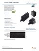
Cannon Trident Connectors
Snap Together - Rectangular
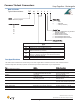
Test Method Criteria of Acceptance
Dielectric Withstanding Voltage 2000 V ac No breakdown
Thermal Shock -55°C to +125°C (-67°F to +257°F), 5 cycles No physical damage
Physical Shock 50 g’s peak, 3 axes, No physical damage.
11 millisecond duration half-sine pulse No loss of continuity >1 sec
Vibration 10 g’s peak, No physical damage,
10-500 Hz, 9 hours No loss of continuity >1 sec
Durability 500 cycles of mating and unmating, No mechanical or
500 mating cycles max electrical defects
Salt Spray 48 hours Shall be capable of mating and unmating
and meet contact resistance requirements
High Temperature Endurance 1000 hours at 125°C (+257°F) Insulation Resistance > 100 MΩ
Humidy Steady State RH 90-95%, 40°C (+104°F), 504 hours Insulation Resistance > 100 MΩ
Moisture Resistance 10 Cycles Insulation Resistance > 100 MΩ
The table below summarizes the results of key tests. Data is applicable to standard connectors with standard contacts.
Variations may affect this data, so please consult factory for further information on your requirements.
Test Specifications
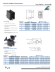
How to Order
Dimensions shown in mm (inch)
Specifications and dimensions subject to change
www.ittcannon.com
8
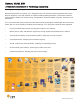
Type
PA Plug; Free
RB Receptacle; For PCB, with Mounting Lugs
RA
Receptacle; Panel Mounting
(delivered without any contacts)
RR
Receptacle, For PCB, 90° Right Angle Mounting
(only for 12 position connectors with machined contacts)
AS Accessory; Receptacle Shroud
AH Accessory; Plug Strain Relief Hood