NEO-DYN 801P5 SMART SWITCHTM INSTALLATION AND OPERATION MANUAL PN 610-0002 Rev D ECO 71349
Manual No. 610-0002 Rev. D Neo-Dyn 28150 Industry Drive Valencia, CA 91355 Tel: (661) 295-4000 Fax: (661) 294-1750 World Wide Web: www.neodyn.com Copyright 2002 ITT Industries Important Information The product warranty applicable to this ITT Neo-Dyn® instrument is as stated on page 41 of this manual. Should any after-delivery problems arise, please contact ITT Neo-Dyn’s Customer Service using the information above. Our normal business hours are weekdays, 7:00 am to 3:30 pm, Pacific Time.
TABLE OF CONTENTS PAGE CHAPTER 1 INTRODUCTION................................................. 1 ABOUT THIS MANUAL......................................................... 4 KEYS ........................................................................................ 4 DISPLAY .................................................................................. 4 CUSTOMER SERVICE............................................................ 4 CHAPTER 2 INSTALLATION ...............................................
TABLE OF CONTENTS PAGE CHAPTER 6 SERIAL COMMUNICATIONS (Z Option) .......35 GENERAL ..................................................................................35 WIRING ......................................................................................35 CHAPTER 7 SPECIFICATIONS..............................................37 STANDARD ...........................................................................37 OPTIONS ...............................................................................
CHAPTER 1 INTRODUCTION The Neo-Dyn® 801P5 Smart-SwitchTM is a solid-state pressure switch designed for a wide range of applications in pneumatic and hydraulic systems up to 3,000 psig. Pressure indication, switch status and operational status are continually displayed on the front panel. The unit can be configured to display pressure readings in a variety of formats.
4-20 mA Output RS232 COM Port Status Indicators Keypad Conduit Connection 1/2-14 NPT Pressure Port 1/4-18 NPT Std 18” free leads #22 AWG Figure 1 Model 801P5 Smart-SwitchTM (Mounting Brackets not Shown) Page 2 Installation and Operation Manual
The standard electrical interface is 22 AWG free leads exiting from a ½” - 14 NPT male conduit connection. The standard pressure connection is ¼” - 18 NPT female; a 7/16” - 20 SAE pressure connection is available as Option E. Output options available for the Smart-SwitchTM include a 4-20 mA analog output (Option V), scalable display units (Option Q), and RS232 communications (Option Z). The RS232 option can be used to configure and monitor the unit remotely. This option includes Windows®-based software.
ABOUT THIS MANUAL The following paragraphs describe the format conventions used in this manual. KEYS Most of the instructions contain directions to press a key, which is one of the blue touchpads on the display surface of the Smart-SwitchTM. When included in instructions, the keys are shown in brackets, as [STORE]. DISPLAY When shown in the text, the LED displays are formatted as 279.3.
CHAPTER 2 INSTALLATION Installation of the Smart-SwitchTM is relatively straightforward. However, the Smart-SwitchTM must be installed by a qualified electrician, in compliance with all local and national electrical codes. Electrical Hazard WARNING Do not make electrical connections while power is on. WARNING Always check for multiple circuits. WARNING Always make sure grounding is adequate.
ELECTRICAL CONNECTIONS Units are supplied with 22 AWG free leads exiting from a ½”-14 NPT male conduit connection. The leads are-color coded and marked. See Figure 2 for AC operation and Figure 3 for DC operation. 4-20 mA output (option letter V) is connected to the 2-pin connector on the top-right of the unit per Figure 4, using the supplied mating connector. This mating connector has solder cups that will take wires as large as #18 AWG. See Chapter 4 for operating instructions.
Figure 2 - Schematic for AC Operation Page 7 801P5 Smart SwitchTM
Figure 3 - Schematic for DC Operation Page 8 Installation and Operation Manual
A B + 4-20 Ma RETURN Figure 4 - Wiring for 4-20 mA Analog Output Page 9 801P5 Smart SwitchTM
A B C DATA SEND DATA RECEIVE SIGNAL GROUND Figure 5 - Wiring for RS-232 Communications Page 10 Installation and Operation Manual
CHAPTER 3 OPERATION & PROGRAMMING This section describes the regular (normal) operation of the Smart-SwitchTM as it monitors pressure after installation and initial setup, and the Programming Mode for changing the settings. Both modes rely on the front panel for information and input. See Figure 6 on the next page. OPERATION MODE To begin operation, apply correct power to the appropriate free leads (there is no on-off switch).
FRONT PANEL CONTROLS Figure 6 The Front Panel, with Function Keys Below the Display Indicators Display The display shows the actual system pressure in normal operation. S1 and S2 (Switch) Indicators The S1 and S2 (red LED's) indicate switch status (illuminated with the relay coil energized or the solid-state switch actuated). Online Indicator The Online indicator (green LED) is lit when the unit is online and active. If the indicator is not lit, the unit is offline.
INPUT CONTROLS S1 and S2 INCR/DECR Push the [S1] and [S2] [INCR] and [DECR] keys to see what values the set points are configured for. MENU Use the [MENU] key to enter program mode. UP/DOWN ARROW The [UP/DOWN ARROW] keys are used to move through the list of submenus. SELECT The [SELECT] key is used to move into the desired submenu. STORE The [STORE] key is used to temporarily save changes made to the current submenu and return to the main menu.
DISPLAYING SET POINTS. Programmed set points can be viewed on the front panel display by pressing the corresponding [S1] or [S2] key. To view the increasing value for Switch 1, press [S1 INCR]. To view the decreasing value for Switch 2, press [S2 DECR]. Figure 7 Press the Incr / Decr Buttons to Display Set Points for S1 / S2 NOTE After 5 seconds of keypad inactivity, the display automatically changes back to the system pressure display. While viewing set points, the output functions remain active.
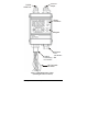
STANDARD VS. WINDOW MODE The terms “Standard” and “Window” describe two methods for setting up the Smart-SwitchTM to monitor pressure. Standard Mode In Standard Mode, illustrated in Figure 8, the SP1i (or SP2i) set point actuates when the pressure being monitored goes above the set value. At this point, the Smart-SwitchTM might turn off whatever electrical power is being applied to a pump, for example, which is increasing or maintaining the pressure.
Deadband The deadband is the separation between the increasing set point and the decreasing set point, as shown in Figure 8. The deadband can be anywhere from 1% to 99% of Full-Scale Output (F.S.O.). In the case above where the Smart-SwitchTM is controlling a pump, a wider deadband reduces the frequency at which the pump cycles on and off.
PROGRAMMING MODE In Programming Mode, you can: • Change the set points • Perform field pressure calibration • Program Window or Standard Mode • Change the password • Program display update time • Program delays for both switches • Scale the readout • Reset the Smart-SwitchTM to factory defaults If your unit includes the 4-20 mA option, you can: • Activate 4-20 mA mode • Calibrate the 4-20 mA • Scale the 4-20 mA output If your unit includes the RS232 option, you can: • NOTE Set the BAU
You can now use the arrow keys to move throughout the menu system. Then: 1. When the menu item you want to change is displayed, press [SELECT]. 2. After changing the value, use the [STORE] key to temporarily save the changes. If you make a mistake while entering values, press the [MENU] key to return to the menu system and restart. 3. To change another item, press the [UP/DOWN ARROW] keys to display that item, and repeat steps 1 and 2. 4.
CHANGING THE SET POINTS To change the set points, press the [MENU] key (See Figure 7). The first menu item is SP1i, for Set point 1, increasing. To change a set point: 1. If you want to change a set point other than SP1i, select the set point by pressing the arrow keys, then press [SELECT]. The furthest right digit will blink. 2. Use the [SELECT] key to move to the digit you want to change. 3. Use the [UP/DOWN ARROW] keys to change the value of the digit. 4.
ADDITIONAL FEATURES To alter the settings of the Smart-SwitchTM, press the [MENU] key and use the [UP/DOWN ARROW] keys to move through the menu. Mode (MOD) Mode allows you to choose between Standard and Window Mode. After MOD is displayed, use the [SELECT] key to enter the Mode submenu and use the [UP/DOWN ARROW] keys to toggle between STD and WIN. Press the [STORE] key to temporarily save your setting.
Scalable Readout: Option Q With this option installed, you can change the scale factor of the display to read in different units of pressure, or in arbitrary numbers that you choose. If your system is set up with pressures in bars, for example, you might want the Smart-SwitchTM display to show bars instead of psig. The r-Hi, r-Lo and .Loc menu functions allow you to scale the readout to your preference. In the following example, millibars are used: You have a scalable 801P5 with the 15psig sensor.
To change the (r-Lo)and (r-Hi): 1. Press the [MENU] key and use the [UP/DOWN ARROW] keys to move through the menu selections to r-Lo. 2. Press [SELECT]. The furthest right digit will blink. 3. Change the digit’s value with the [UP/DOWN ARROW] keys. 4. When the value is correct, press the [SELECT] key to move to the next digit and repeat step 3. Repeat for each digit until you have the correct value for r-Lo. 5. Use the [STORE] key to temporarily save the changes and return to the main menu. 6.
Pressure Calibration (PCAL) You can do a field pressure calibration using this function. After PCAL is displayed, use the [SELECT] key to enter the submenu. LO-P will be displayed for one second, and then the switch’s interpretation of the actual pressure will be displayed. Apply 0.0 psig to the unit. Use the [UP/DOWN ARROW] keys to adjust the pressure display to zero psig. Press the [STORE] key.
NOTE If you have the 4-20 mA analog option, there are three additional menu items that are reset. These are: LooP is set to on. ScHi is set to F.S.O. ScLo is set to zero. These three menu items are discussed in Chapter 4, Analog Option.
CHAPTER 4 ANALOG OPTION The analog option (V option) for the 801P5 allows you to equate pressure with electrical current. If your Smart-SwitchTM includes this option, the 4-20 mA output can be scaled; see page 27.
4-20 MILLIAMPERE OUTPUT CALIBRATION (4CAL) The 801P5 is factory calibrated to generate 4 mA when the pressure sensor is at 0 psig, and 20 mA when rated pressure is applied. Tolerances in your signal conditioning equipment may result in readings varying from these values, so you can calibrate the 4-20 mA output as follows to correct these readings. NOTE 1. Connect a calibrated milliammeter to the 4-20 mA output. 2. Press [MENU], then press the [UP/DOWN ARROW] key until 4CAL is displayed. 3.
4-20 MILLIAMPERE OUTPUT SCALING The 4-20 mA output is scaleable, allowing 4 mA to represent any pressure between 0% and 66% F.S.O., and 20 mA to represent any pressure between 33% and 100%F.S.O. This feature is helpful in systems where the normal operating pressure falls within the pressure range of the unit. For example, let’s assume that the Smart-SwitchTM has a pressure range of 0 to 100 PSIG, and the process that it is monitoring operates between 20 and 80 PSIG.
Page 28 Installation and Operation Manual
CHAPTER 5 TROUBLESHOOTING It is unlikely that you’ll have any problems with the Smart-SwitchTM. However, just in case, this chapter contains information to help diagnose and correct any error messages you may see. ERROR MESSAGES Below are error messages that you may see during operation or programming, along with brief descriptions of how to correct them. If you see an error that is not listed here, contact Neo-Dyn Customer Service. The contact information is located in Chapter 1.
Display Shows EROR This message might appear while programming the 801P5 Smart-SwitchTM. The meaning depends on what is being programmed. Following are the possible causes and solutions. Incorrect password entered You have entered an incorrect password. Re-enter the correct password. If you have lost or forgotten the password, contact Neo-Dyn Customer Service for assistance. Incompatible switch set points. You have entered incompatible set points.
Pressure Calibration (PCAL) or Analog Output Calibration (4Cal) is incorrect. If you change the value for pressure or analog output calibration more than 4% of the F.S.O. from the original factory values, this error occurs. Contact Neo-Dyn Customer Service for assistance. NOTE If the power to the unit is turned off and then back on, the unit will function using the new values. However, this is not recommended, as a calibration error this large indicates imminent component failure.
Display alternates between OPEN and LOOP and the pressure reading The OPEN LOOP message is displayed with the V option (4-20 mA analog output) in the following circumstances: The analog loop is turned on, but nothing is connected to the analog output connector. In this case, press the [MENU] key to enter the programming mode. Use the [UP/DOWN ARROW] keys to set this option to OFF. Press the [STORE] key to temporarily save the change.
Display shows E-96 This code indicates an internal A/D reading that is out of its allowable tolerance. Although this can indicate an internal component failure, the most common cause of this error is vacuum applied to the pressure port of the unit. If the cause is vacuum, once the pressure returns to near zero, the unit will return to monitoring and controlling. If the cause is internal component failure, contact Neo-Dyn Customer Service for assistance.
Page 34 Installation and Operation Manual
CHAPTER 6 SERIAL COMMUNICATIONS (Z Option) GENERAL The Smart SwitchTM with the Z Option installed is capable of RS232 communications with an IBM compatible computer. This option includes Windows 3.x / 95 / 98 / Me / 2000 compatible software, which allows remote monitoring and programming of the Smart Switch, as well as data tracking functions. To install the software, follow the Setup instructions on the diskette label. Once it is installed, the Help menu provides detailed operating instructions.
Page 36 Installation and Operation Manual
CHAPTER 7 SPECIFICATIONS This section shows the standard specifications and available options for the Neo-Dyn® 801P5 Smart-SwitchTM . STANDARD Interface The Smart-SwitchTM weighs approximately 6 pounds (2.7 kg).
Part Number The part number contains information about which configurations and options are included in your Smart-SwitchTM. To determine the pressure range, electrical rating, and options, compare the part number of your unit with the information below. 801P 5 ## X X X Model Series Wetted Material Range Number Input Power Switch Type Options Figure 10 Part Number Breakdown Pressure Rating Information Max Proof Range Operating Increasing Deadband Minimum Range Decreasing Operating Pressure No.
Range Operating Increasing Deadband Minimum Max Proof No. Range Range Decreasing Operating Pressure Percent of Setpoint Pressure bar bar Full Scale bar bar bar 22 0 - 350 mB 7 - 350 mB 24 0 - 1000 20 - 1000 mB mB 1-99 3.5 mB 0.86 1.7 1-99 10 mB 2.6 5.1 25 0-2 0.04 - 2 1-99 0.02 5.2 10.3 27 0 - 6.5 0.013 - 6.5 1-99 0.065 17.2 34.4 29 0 - 17 0.34 - 17 1-99 0.17 43.1 51.7 31 0 - 35 0.7 - 35 1-99 0.35 103 103 32 0 - 65 1.3 - 65 1-99 0.
Standard Electrical Ratings are: Electrical Rating Code Input Power A 90 - 130 VAC 50/60 Hz E 180 - 260 VAC 50/60 Hz D 18 - 30 VDC The Switch Types are: Switch Code Switch Type Switch Rating Leakage Current A Solid State SPDT 12-140 VAC 3 Amp Resistive 5 mA max D Solid State SPDT 5-60 VDC 3 Amp Resistive 1 mA max R Relay SPDT 115 VAC 24 VDC 3 Amp Resistive N/A OPTIONS The 801P5 options are listed below.
WARRANTY INFORMATION A. Warranty: ITT Industries (ITT) warrants that at the time of shipment, the products manufactured by ITT Neo-Dyn and sold hereunder, will be free from defects in material and workmanship and will conform to the specifications furnished or approved by ITT. B. Warranty Adjustment: If any defect within this warranty appears, the Buyer shall notify ITT immediately.