
Heat Pump User Manual

4
12. On frame-mounted units, tighten foundation, pump
and driver hold-down bolts before connecting piping
to pump.
13. Avoid unnecessary fittings. Select sizes to keep fric-
tion losses low.
14. After completing piping, rotate unit by hand to check
for binding. Note: A screwdriver slot or flats are pro-
vided in end of motor shaft.
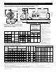
3. Alignment
1. No field alignment is necessary on close-coupled
pumps.
2. Even though the pump-motor unit may have a factory
alignment, in transit this alignment could be disturbed
and must be checked prior to running.
3. Check the tightness of all hold-down bolts before
checking the alignment.
4. If re-alignment is necessary, always move the motor.
Shim as required.
5. Final alignment is achieved when parallel and angular
requirements are achieved with both pump and motor
hold down bolts tight.
ALWAYS RECHECK BOTH
ALIGNMENTS AFTER MAKING
ADJUSTMENTS.
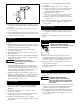
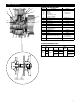
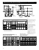
6. Parallel misalignment exists when the shafts are not
concentric. Place dial indicator on one hub and rotate
this hub 360º while taking readings on the outside
diameter of the other hub. Parallel alignment occurs
when Total Indicator Reading is .005" or less.
7. Angular misalignment exists when the shafts are not
parallel. Place dial indicator on one hub and rotate this
hub 360º while taking readings on the face of the
other hub. Angular alignment is achieved when Total
Indicator Reading is .005" or less.
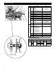
4. Suction Piping
1. Low static lift and short, direct suction piping is
desired. For suction lift over 15 feet, consult pump
performance curve for Net Positive Suction Head
Required.
2. Suction pipe size must be at least equal to suction
connection of pump.
3. If larger pipe is used, an eccentric pipe reducer (with
straight side up) must be used at the pump.
4. Installation with pump below source of supply:
4.1. Install isolation valve in piping for inspection and
maintenance.
4.2. Do not use suction isolation valve to throttle
pump!
5. Installation with pump above source of supply:
5.1. To avoid air pockets, no part of piping should be
higher than pump suction connection. Slope
piping upwards from liquid source.
5.2. All joints must be airtight.
5.3. Foot valve to be used only if necessary for prim-
ing, or to hold prime on intermittent service.
5.4. Suction strainer open area must be at least triple
the pipe area.
6. Size of inlet from liquid source, and minimum submer-
gence over inlet, must be sufficient to prevent air
entering pump.
5. Discharge Piping
1. Arrangement must include a check valve located
between a gate valve and the pump. The gate valve is
for regulation of capacity, or inspection of pump or
check valve.
2. If reducer is required, place between check valve and-
pump.
6. Rotation
DO NOT PLACE HANDS IN PUMP
WHILE CHECKING MOTOR
ROTATION. TO DO SO WILL CAUSE
SEVERE PERSONAL INJURY.
1. Pumps are right-hand rotation (Clockwise when
viewed from the driver end). Switch power on and
off. Observe shaft rotation. On frame-mounted units,
check rotation before coupling pump to motor.
2. Single-Phase: Refer to wiring diagram on motor if
rotation must be changed.
3. Three-Phase: Interchange any two power supply leads
to change rotation.
7. Operation
1. Before starting, pump must be primed (free of air and
suction pipe full of liquid) and discharge valve par-
tially open.
PUMPED LIQUID PROVIDES
LUBRICATION. IF PUMP IS RUN
DRY, ROTATING PARTS WILL SEIZE
AND MECHANICAL SEAL WILL BE
DAMAGED.
2. Make complete check after unit is run under operating
conditions and temperature has stabilized. Check for
expansion of piping. Check coupling alignment.
3. Do not operate at or near zero flow. Energy imparted
to the liquid is converted into heat. Liquid may flash
to vapor. Rotating parts require liquid to prevent scor-
ing or seizing.
CAUTION
Hazardous Machinery
WARNING
CAUTION