
Data Sheet


Data Sheet
6141 Running Springs Rd
San Jose, CA 95135
www.ivativ.com
Email: info@ivativ.com
Ph.: (408) 893 7812
Page 8 of 24
August 3, 2022
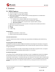
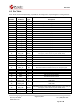
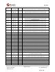
4.2 Pin Table
Note: Unless mentioned specifically, any GPIO can be configured to required digital or analog interface.
Pin
Number
RENO
Pin Name
Pin
Type
Description
1
NC
No Connect
2
LED1/RED
O
System status signal. Active low.
3
LED3/BLUE
O
System status signal. Active low.
4
NC
No Connect
5
NC
No Connect
6
LED2/GREEN
O
System status signal. Active low
7
GPIO_7
I/O
General purpose IO
8
GPIO_8
I/O
General purpose IO
9
nReset
I
Active low reset
10
GPIO_10
I/O
General purpose IO
11
GPIO_11
I/O
General purpose IO
12
GPIO_12
I/O
General purpose IO
13
GPIO_13
I/O
General purpose IO
14
GPIO_14
I/O
General purpose IO
15
GND
Ground
Ground
16
VDD_nRF
Power
3.3V DCDC output Power supply. When 5V input is used, this pin
can supply 3.3V accessories (max 20mA drive)
17
GPIO_17
I/O
General purpose IO
18
NC
No Connect
19
NC
No Connect
20
UART_TXD
O
UART TX Data
21
UART_RXD
I
UART RX Data
22
GPIO_22
I/O
General purpose IO.
Recommended for Standard drive, low frequency I/O
23
GPIO_23
I/O
General purpose IO
24
GPIO_24
I/O
General purpose IO
25
NFC1
I
NFC Antenna Connection
26
NFC2
I
NFC Antenna Connection
27
UART_DTR
O
UART DTR
28
UART_DSR
I
UART DSR
29
VDD_nRF
Power
3.3V DCDC output Power supply. When 5V input is used, this pin
can supply 3.3V accessories (max 20mA drive)
30
GND
Ground
Ground
31
SPI_MISO
O
SPI MISO