copertina NEF series electronic 20-11-2006 10:04 Pagina 1 C M Y CM MY CY CMY K USE AND MAINTENANCE USO E MANUTENZIONE UTILISATION ET ENTRETIEN BETRIEB UND WARTUNG USO Y MANTENIMIENTO NEF SERIES E LECTRONIC INJECTION S YSTEM MARINE ENGINES Publication edited by Marketing - Adv.
NEF SERIES INTRODUCTION ELECTRONIC INJECTION SYSTEM N40 ENT M25 N60 ENT M37 N60 ENT M40 N67 ENT M45 The contents of this manual refer to the standard configuration of the engine, and the illustrations are purely indicative. Some instructions are provided by giving the sequence of operations to be carried out in order to allow the engine and/or its fittings to perform in a certain way.
CONTENTS Page Page GENERAL INFORMATION . . . . . . . . . . . . . . . . . . . . . . . . . . . . . .3 Guarantee . . . . . . . . . . . . . . . . . . . . . . . . . . . . . . . . . . . . . . . . . . . . . .3 Spare Parts . . . . . . . . . . . . . . . . . . . . . . . . . . . . . . . . . . . . . . . . . . . . .3 Liability . . . . . . . . . . . . . . . . . . . . . . . . . . . . . . . . . . . . . . . . . . . . . . . . .3 Safety . . . . . . . . . . . . . . . . . . . . . . . . . . . . . . . . . . . . . . . . . . .
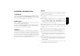
SAFETY GUARANTEE The following information is intended to encourage caution when using the engine, so as to avoid damage to persons or property as a result of improper or incorrect behaviour. In order to ensure that your engine gives the best possible performance and to take advantage of the IVECO MOTORS guarantee, you must follow the indications provided in this publication with great care; failure to do so may result in invalidation of the guarantee.
ENGINE TECHNICAL DATA N40 ENT M25 The technical code and serial number are indicated on a plate, which is located on different parts of the engine, according to the model: flywheel casing, tappet cover, coolant tank. Code N40 ENT M25 Engine family F4 Cycle 4-stroke diesel Number and arrangement of cylinders 4, in line Bore x stroke 102 x 120 mm Total displacement 3.
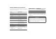
ENGLISH 04_363_N 04_364_N Engine NEF N40 ENT M25 Engine NEF N40 ENT M25 1. Exhaust gas and sea water discharge - 2. Turbocharger - 3. Engine coolant-sea water heat exchanger - 4. Coolant outlet manifold from engine - 5. Oil filter - 6. Lifting U-bolt - 7. Coolant filler cap 8. Thermostat valve location - 9. Alternator - 10.
ENGINE TECHNICAL DATA N60 ENT M37 / M40 The technical code and serial number are indicated on a plate, which is located on different parts of the engine, according to the model: flywheel casing, tappet cover, coolant tank. Code N60 ENT M37 / M40 Engine family F4 Cycle 4-stroke diesel Number and arrangement of cylinders 6, in line Bore x stroke 102 x 120 mm 3 Total displacement 5.
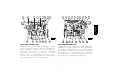
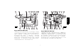
2 3 4 5 6 7 8 1 9 2 3 4 5 6 7 8 9 10 ENGLISH 1 04_352_N 04_353_N 16 15 14 13 12 11 10 18 17 16 15 14 13 12 11 Engine NEF N60 ENT M37/M40 Engine NEF N60 ENT M37/M40 1. Exhaust gas and sea water discharge - 2. Turbocharger - 3. Engine coolant-sea water heat exchanger - 4. Coolant outlet manifold from engine - 5. Oil filter - 6. Lifting U-bolt - 7. Coolant filler cap 8. Thermostat valve location - 9. Alternator - 10.
ENGINE TECHNICAL DATA N67 ENT M45 The technical code and serial number are indicated on a plate, which is located on different parts of the engine, according to the model: flywheel casing, tappet cover, coolant tank.
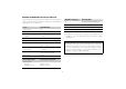
2 3 4 5 6 7 8 1 9 2 3 4 5 6 7 8 9 10 ENGLISH 1 04_352_N 04_353_N 16 15 14 13 12 11 10 18 17 16 15 14 13 12 11 Engine NEF N67 ENT M45 Engine NEF N67 ENT M45 1. Exhaust gas and sea water discharge - 2. Turbocharger - 3. Engine coolant-sea water heat exchanger - 4. Coolant outlet manifold from engine - 5. Oil filter - 6. Lifting U-bolt - 7. Coolant filler cap 8. Thermostat valve location - 9. Alternator - 10.
SIGNS Certain warning signs are affixed to the engine, and their meanings are indicated below. NOTE: The signs with an exclamation mark on them underline a potential danger. Lifting point (engine only). Danger of burning: Expulsion of hot water under pressure. Fuel Cap (on the fuel tank, if there is one). Danger of burning: Presence of high temperature parts. Oil Cap. Danger of fire: Fuel present. Danger of impact or catching on moving parts: Presence of fans, pulleys, belts or the like.
STARTING AND STOPPING THE ENGINE PRELIMINARY CHECKS For vessels equipped with instrument panels that are not manufactured by IVECO MOTORS The start-up and shut-down operations described below apply to an onboard control panel manufactured by IVECO MOTORS; if the vessel is fitted with an instrument panel that has been customised by the Boatbuilder or Fitter, these operations may vary according to the various choices made during construction.
STARTING AND STOPPING THE ENGINE FROM THE ANALOGUE CONTROL PANEL 2 Procedure for start-up from the main IVECO MOTORS control panel (supplied on demand) 5 4 Make sure that the electrical switch indicating ENGINE ROOM BRIDGE on the Relay Box unit (normally located in the engine room) is in the BRIDGE position, then proceed as follows: 1. Lift the protective cover over the key switch (8), insert the key and turn it to the right to position 8B. 2.
2 1 1. Enable the secondary control panel, by turning the key switch on the main panel to position 8B (see warnings and procedure given in previous paragraph). 2. Wait for the beeper to stop sounding and for the alarm indicators on the indicator module (3) to switch off, with the exception of the “alternator recharge” and “low oil pressure” indicators.
Stopping the engine Before stopping the engine it is recommended you run it for a few minutes at minimum speed with no load; this will allow the temperature to drop evenly and will avoid harmful thermal shocks. A. The engine is normally stopped from the main IVECO MOTORS control panel by turning the key switch to the rest position 8A or by turning a similar command on the customised control panel. B. The IVECO MOTORS secondary control panel is stopped by pressing the red button (6) on the control panel.
RECOGNISING ALARMS IVECO MOTORS on-board control panels with analogue instruments are fitted with an electronic module that includes the indicator lights and the interface, timer and alarm storage circuits. The figure illustrates the dial and the key indicates the meaning of the alarm signals sent by all the indicator lights; some types of engine and relevant equipment only make some of the above mentioned functions available.
STARTING AND STOPPING THE ENGINE FROM THE DIGITAL CONTROL PANEL 3 Procedure for start-up from the main IVECO MOTORS control panel (supplied on demand) 3 4 Make sure that the electrical switch indicating ENGINE ROOM BRIDGE on the Relay Box unit (normally located in the engine room) is in the BRIDGE position, then proceed as follows: 1. Lift the protective cover over the key switch (8), insert the key and turn it to the right to position 8B. 2.
Procedure for start-up from IVECO MOTORS secondary or fly-bridge control panel (supplied on demand) 3 1. Enable the secondary control panel, by turning the key switch on the main panel to position 8B (requirements and procedure given in previous paragraph). 2. Wait for the beeper to stop sounding and for the alarm indicator lights to switch off, with the exception of the “Alarm malfunction” and “Low oil pressure” indicators.
Stopping the engine RECOGNISING ALARMS Before stopping the engine it is recommended you run it for a few minutes at minimum speed with no load; this will allow the temperature to drop evenly and will avoid harmful thermal shocks. A. From the main IVECO MOTORS control panel: turn the key switch to the rest position 8A. B. From the secondary IVECO MOTORS control panel: press the red STOP button (8).
Operation Detail of the main control panel When the key switch is turned to position 8B an efficiency test will be performed on all the indicator lights, lasting 5 seconds, with the exception of the “Pre-lubrication”, “Pre-post heating”, “EDC electronic injection system malfunction” indicators, and simultaneously the beeper sounds; It is possible to stop the beeper before the end of the test, by pressing the relevant button.
If the set value does not correspond with the one foreseen for the type of oil being used (see requirements in the sections on REFUELLING and FREQUENCY) proceed as follows: - After displaying the value in hours set previously, release the buttons and press just the “Scroll select” button (10) repeatedly until the prescribed value (as indicated in the section FREQUENCY) is shown and flashes, after which press the “Prog” button (9) to confirm the value and start the new count.
MANAGING THE ENGINE FROM THE RELAY BOX Start-up procedure 1 2 Running speed management procedure Press button 2 in the START position, with the engine turning, to accelerate and decelerate; each time the button is pressed the engine will accelerate or decelerate in sequence. 1. To accelerate: press and hold button 2 in the START position until the required engine speed is achieved, then release it; the speed will be maintained. 2.
FOR PROPER USE OF THE ENGINE SPECIAL WARNINGS Do not continue to press the starter, when the engine has started. Do not remain in dock while waiting for the engine to warm up, but after starting, commence navigation at low speed; the working temperature will be reached properly with the engine running at medium speeds. Do not operate the engine at minimum speed for long periods, as this encourages the production of harmful exhaust and does not guarantee optimum performance.
Water in the fuel pre-filter Alternator malfunction It is a good rule to drain the water from the filters, before the relevant indicator comes on. Avoid using the engine with the fuel tank only a small reserve of fuel; this encourages the formation of condensation and makes it more likely you will suck up dirt or air, resulting in engine stoppage. Check it or have it checked periodically for cleanliness, wear and proper tensioning of the drive belt.
REFUELLING Parts to be supplied N40 ENT litres (kg) N60 ENT litres (kg) 21.5 24.5 Oil consumption is considered acceptable when it reaches a maximum of 0.5% of fuel consumption. (3)The amounts indicated refer to initial refuelling, and include filling the engine, sump and filter. (4)Only use normal commercial diesel fuel (EN 590 standards). Do not use additives. Do not use fuels derived from the synthesis of organic substances and vegetable oils (Biodiesel).
• replacing or topping up lubricant (hot engine oil may cause burns and scalds. Only carry out these operations when the oil has dropped to a temperature of below 50°C). When working in the engine compartment, pay particular attention to how you move, to avoid contact with moving parts or high temperature components. Wear goggles and use high pressure air jets (maximum air pressure used to clean is 200 kPa (2 bar, 30 psi, 2 kg/cm2).
CAUTION! Planned maintenance Do not carry out maintenance operations when the electric power supply is turned on: always check to ensure that the appliances are properly earthed.
Frequency Check wear in sea water pump rotor 900 hours Replace belt 1200 hours or 2 years Clean heat exchangers 2 years (6) Clean the turbocharger 2 years (5) Adjust play in valves-rocker arms 3000 hours I) Maximum period when using good quality fuel , (EN 590 standard); this is reduced if the fuel is contaminated and alarms are triggered due to blockage of the filters and presence of water in the pre-filter. When blockage of the filter is indicated, it must be replaced.
REQUIREMENTS HOW TO PROCEED 1. Do not disconnect the batteries with the engine running. 2. Do not carry out arc welding operations in the vicinity of the engine without first removing electrical cables and electronic units. 3. After each maintenance operation involving disconnection of the battery/batteries, make sure that the terminals have been properly locked onto the poles. 4. Do not use battery chargers to start the engine. 5. Disconnect the on-board network battery/batteries when recharging. 6.
Draining water from the fuel pre-filter Check the oil level in the marine gear following the indications provided in the marine gear Manufacturer's manual. The high risk of refuelling with fuel that is polluted by foreign bodies and water means that it is necessary to perform this control even if no alarm is shown on the on-board control panel. Proceed with the engine stopped. Place a container under the pre-filter to collect the fluid.
Contact specialised technical staff if the battery needs recharging. Have the efficiency of the battery recharging system tested if a voltage of less than 11 V (for 12 V rated systems) or 22 V (for 24 V rated systems) is detected with the engine running. On this occasion, make sure that the terminals and clamps are clean, properly locked and protected by vaseline. Cleaning the air filter Remove the filter by loosening the screws (4) indicated in the figure.
Only proceed with the engine stopped and at a low temperature: Provide suitable containers to ensure that no water is dispersed inside the vessel during removal of the anodes. Remove the anodes, unscrewing them from their housings (see location in the section ENGINE TECHNICAL DATA). Make sure that corrosion has not exceeded 50% of the volume of zinc. If this is the case, change them. Replace the anodes in their housings, locking them to the prescribed torque.
Changing the fuel filter Only proceed with the engine stopped and at a low temperature Remove the filter by unscrewing it. Check that the new filter has performance levels that satisfy the needs of the engine (e.g. by comparing them with the old one. See section on FREQUENCY). Damp the new filter seal with diesel or engine oil. Hand screw the new filter into place until the seal gasket touches the support, then lock by a further 3/4 of a turn.
Check tension and state of the auxiliary member drive belt Only proceed with the engine stopped and at a low temperature Remove the pre-filter by 1 unscrewing it. Check that the new filter has performance levels that satisfy the needs of the engine (e.g. by comparing them with the old one). 2 Damp the new filter seal with diesel or engine oil. Hand screw the new filter into place until the seal gasket touches the support, then lock by a further 3/4 of a turn.
Replace coolant Only proceed with the engine stopped and at a low temperature, so as to avoid the risk of burning. Provide suitable containers to ensure that no coolant is dispersed into the environment. Remove the plugs on the circuit components and wait until the circuit has drained completely (the location of plugs is given in the section ENGINE TECHNICAL DATA). After emptying, replace the plugs in their housings, making sure that the seal rings are all undamaged.
DISPOSAL OF WASTE The operations necessary to embark and disembark the engine must only be carried out by technicians from Authorised Service Centres. When lifting the engine only, use the U-bolts indicated in this manual in the section ENGINE TECHNICAL DATA and marked on the engine with special stickers. Lifting must be carried out using a rocker arm that keeps the metal cables supporting the engine parallel, using all the U-bolts provided simultaneously; the use of a single U-bolt only is not allowed.
LONG PERIODS OF INACTIVITY PREPARING THE ENGINE PERIOD OF INACTIVITY FOR A 7. Drain the residual 30/M protective oil from the sump. This oil can be used again for a further 2 preparation operations. 8. Fit signs reading ENGINE WITHOUT OIL to the engine and to the on-board control panel. 9. Drain the coolant, if it has not been mixed with suitable antifreeze and corrosion inhibitors, and affix a sign to indicate the fact.
RESTARTING THE ENGINE AFTER A LONG PERIOD OF INACTIVITY ENGLISH 1. Drain the residual 30/M protective oil from the sump. 2. Fill the engine, as prescribed, with lubricant of the type and amount indicated in the table REFUELLING. 3. Drain the CFB protective fluid from the fuel circuit, carrying out this operation as indicated under point 3. of PREPARING THE ENGINE FOR A LONG PERIOD OF INACTIVITY. 4.
ENGINE MALFUNCTIONS CAUTION! The electronic unit overseeing management and control of all operation of the engine is capable of recognising any malfunctions that may occur, and of adopting strategies that will allow you to navigate in full safety. The event, signalled by light-up of the EDC MALFUNCTION indicator on the on-board control panels, results in programmed limitation of power within certain thresholds, set according to the severity of the case.
EMERGENCIES ON BOARD 1. Extinguish any flames on the burned person's clothing, by: • throwing water over them; • using a powder fire-extinguisher, without directing the jet at the person's face; • covering with blankets or rolling the victim on the ground. 2. Do not attempt to remove pieces of clothing that may have stuck to the skin; 3. In the case of scalding, immediately but carefully remove any clothing that may be soaked in the hot liquid; 4.
Electrocution Caustic burns The engine's electrical 12 V or 24 V electrical system does not involve the risk of electrocution, however, in the event of a short-circuit caused, for example, by a metal tool, there is a risk of burning due to overheating of the object through which the electrical current runs. In these circumstances: 1. Remove the object that caused the short-circuit, using means that provide sufficient heat insulation. 2. Switch off the power at the main switch, if there is one.
& ENGLISH 6$( : 6$( : 6$( 6$( 6$( : 6$( : 6$( : 6$( : PLQHUDO EDVH 6$( : VHPLV\QWKHWLF EDVH 6$( : VHPLV\QWKHWLF EDVH 6$( : V\QWKHWLF EDVH 6$( : V\QWKHWLF EDVH 41 )