SOFIM S30 ENT M23 4 cylinders in line Diesel Cycle For marine applications INSTALLATION DIRECTIVE T E C H N O L O G I C A L E X C E L L E N C E MAY 2006 EDITION
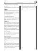
S30 ENT M23 INSTALLATION DIRECTIVE FOREWORD We strongly recommend that you carefully read the indications contained in this document: compliance with them protects the engine against irregular operation and assures its reliability, safeguarding sea-going and maintenance personnel against accident hazards.
MAY 2006 INSTALLATION DIRECTIVE S30 ENT M23 CONTENTS Page 1. WARNINGS AND CAUTIONS 4 2. ENGINE PARTS AND COMPONENTS 6 3. INSTALLATION OVERVIEW 8 4. GENERAL INSTALLATION CRITERIA 9 5. TECHNICAL DATA FOR INSTALLATION 10 6. IDENTIFICATION DATA 12 7. COMPONENTS SUPPLIED WITH THE ENGINE 13 8. FUEL LINE 14 9. ELECTRICAL EQUIPMENT 17 10. MAIN ANALOG INSTRUMENT PANEL 26 11. SECONDARY ANALOG INSTRUMENT PANEL 30 12. DRILLING PLANS FOR ANALOG PANELS 31 13.
S30 ENT M23 INSTALLATION DIRECTIVE MAY 2006 1. WARNINGS AND CAUTIONS To obtain the best engine performance, it is essential not to deviate from the mission profile for which it was produced and set up. The engine must not be used for purposes other than those stated by the manufacturer. IVECO MOTORS is willing to examine any need for particular installations beforehand.
MAY 2006 INSTALLATION DIRECTIVE o Do not cause sparks in the attempt to verify the presence of electrical voltage. o Do not draw fuel through unfiltered lines. o Do not clean the engine and its parts with corrosive or abrasive detergent substances, to avoid compromising the integrity of electrical connections. o The engine fluids and air, water, and oil filters discarded after use must be properly stored and delivered to appropriate collection centers.
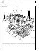
INSTALLATION DIRECTIVE S30 ENT M23 MAY 2006 2. ENGINE PARTS AND COMPONENTS Figure 1 5 6 7 8 7 4 9 3 2 1 12 11 05_003_S 10 1. Engine coolant discharge cap - 2. Electric starter motor - 3. Tube bundle engine coolant/sea water heat exchanger - 4. Exhaust gas and sea water discharge pipeline - 5. Engine coolant tank - 6. Coolant refill cap - 7. Lifting eyebolts - 8. Oil refill cap - 9. Sea water pump actuation pulley - 10. Auxiliary belt automatic tensioner - 11. Alternator - 12.
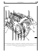
INSTALLATION DIRECTIVE MAY 2006 S30 ENT M23 Figure 2 11 12 13 14 10 9 15 17 8 16 17 7 05_002_S 6 5 4 3 2 1 1. Engine coolant discharge cap location - 2. Combustion air filter - 3. Sacrificial anode - 4. Throttle potentiometer - 5. Combustion air-sea water heat exchanger - 6. Oil dipstick - 7. Location of common rail high pressure injection pump - 8. Sea water pump - 9. Sea water inlet - 10. Manual lubricating oil extraction pump - 11. Oil vapor separator - 12.
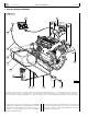
INSTALLATION DIRECTIVE S30 ENT M23 MAY 2006 3. INSTALLATION OVERVIEW Figure 3 1 2 13 12 10 3 11 10 9 06_005_S 8 7 6 5 4 1. Indicator and control panel - 2. Electrical panel with relay box and EDC electronic unit - 3. Exhaust gas and sea water discharge 4. Filtered sea water intake - 5. Decanter filter - 6. Fuel feed pipe to the high pressure pump - 7. Fuel electric pump - 8. Fuel prefilter - 9. Fuel filter - 10. Fuel priming pipe - 11. Fuel return pipe to the tank - 12.
MAY 2006 INSTALLATION DIRECTIVE S30 ENT M23 4. GENERAL INSTALLATION CRITERIA Accessibility The engine must be located in such a way as to allow filling and draining engine liquids when doing servicing operations. Anchoring If anchoring is accomplished by interposing shock mounts, they must be able to support the engine’s mass and the longitudinal thrust exerted by the propeller shaft in motion. If rigid mounting is adopted, particular care must be given to support alignment and co-planarity.
S30 ENT M23 INSTALLATION DIRECTIVE MAY 2006 5. TECHNICAL DATA FOR INSTALLATION Combustion and ventilation air when underway Static vacuum allowed downstream of the air filter kPa mm H2O ≤ 3,5 ≤ 350 Combustion air flow rate m3/h ≥ 710 Engine room ventilation air flow rate (excluding combustion air) m3/h ≥ 3590 Static vacuum allowed in the engine room kPa mm H2O ≤ 0,1 ≤ 10 Temperature allowed in the engine room °C ≤ 45 Temperature increase in the engine room to ext.
INSTALLATION DIRECTIVE MAY 2006 11 S30 ENT M23 Power takeoffs (optional) 1-race front pulley for “V” belts Reference diameter mm 83 Race dimension mm 10 Power available at 1000 rpm (*) kW ≤1 Power available at 2000 rpm (*) kW ≤2 Radial force resulting from belt tension (*) N ≤ 400 (*) These values are valid for driving to the side opposite to that of the sea water pump Dimensions ¬ ¬ -!8¬ ¬ -).
S30 ENT M23 INSTALLATION DIRECTIVE MAY 2006 6.
INSTALLATION DIRECTIVE MAY 2006 S30 ENT M23 13 7. COMPONENTS SUPPLIED WITH THE ENGINE Figure 7 5 *&# 6 0& ! : 7 - 06_019_S 4 1. Connectors to be assembled - 2. Conductor terminals - 3. Gaskets to be fitted on individual wires - 4. PF connector rear cover 5. Fuel electric pump - 6. Fuel pre-filter - 7. Fuel filter - 8. Components to replace fittings mounted on the fuel filter.
S30 ENT M23 INSTALLATION DIRECTIVE MAY 2006 8. FUEL LINE Figure 8 3 2 1 4 5 High pressure Low pressure 6 06_006_S 1. Low pressure mechanical feeding pump and high pressure common rail injection pump - 2. Electro-injector - 3. Common rail 4. Pre-filter - 5. Fuel electric pump - 6. Filter.
INSTALLATION DIRECTIVE MAY 2006 15 S30 ENT M23 Fuel supply system scheme Figure 9 4 5 6 3 2 1 M 12 06_007_S 11 10 9 8 7 1. Low pressure limiter valve - 2. Pressure regulating electric valve - 3. High pressure radial pump - 4. Pressure sensor - 5. Common rail - 6. Electro-injector - 7. Fuel tank - 8. Pre-filter - 9. Fuel electric pump - 10. Filter - 11. Vent fitting - 12. Low pressure mechanical feed pump. Hydraulic connections Figure 10 1 2 06_020_S 1.
S30 ENT M23 INSTALLATION DIRECTIVE Preparation of the fuel filter support Figure 11 1 2 3 2 06_010_S 1. Screw - 2. Seal washers - 3. Rubber holder fitting. The filter support must be prepared by replacing fuel inlet and outlet fittings with the supplied ones. Following the removal of the fittings on the support, Rubber holder fitting must be mounted on the screws by fitting seal washers as shown in the picture. Tighten the screws.
INSTALLATION DIRECTIVE MAY 2006 17 S30 ENT M23 9. ELECTRICAL EQUIPMENT Figure 12 1 2 3 4 5 6 7 8 13 12 06_012_S 11 10 9 1. Engine wiring - 2. +BATT/CC terminal - 3. Power line for electric starter motor and alternator - 4. Indicator and control panel - 5. Extension harness - 6. Engine pre-heating glow plugs electronic control unit - 7. Fuse holder for the engine pre-heating glow plugs electronic control unit - 8. ECU EDC connectors - 9. Relay box - 10. Diagnostic tool connector - 11.
INSTALLATION DIRECTIVE S30 ENT M23 MAY 2006 Synoptic Figure 13 Throttle position sensor Indications and alarms sensors Electro-injectors EDC components Alternator Electric starter motor 3 ¬%.4¬- BOX RELÉ 0% ## *" *&# ! BATTERIA %$# " 1 2 06_030_S 3 4 1. Connector for instrument panel connection wire harness - 2. Engine wire harness - 3. Connector for fuel filter wiring - 4. Power line.
Engine wire harness -- % % % % 6 / # ( 02 *&# ' ' ' ' 7 0% :( " ! ## - : ! 0& & "/8 ¬ 2%,³ + + + + + ¬ %$#¬"¬ &¬ &¬ &¬ &¬ &¬ * + ¬ %$#¬!¬ INSTALLATION DIRECTIVE Figure 14 A. Fuel temperature sensor for EDC - B. Drive shaft sensor for EDC - C. Camshaft sensor - F. Engine coolant temperature sensor for EDC - ECF. Connector for the engine stopping functions if stressed - ECM. Connector for the engine stopping function if stressed - H.
INSTALLATION DIRECTIVE S30 ENT M23 Power supply line Supplementary services battery To assure that the engine can be started with a sufficient quantity of energy, it is advisable to provide for the installation of a supplementary battery, dedicated to supplying power to the on-board electrical services. The power line to recharge it may be constructed according to the indications provided in Chapter 22.
INSTALLATION DIRECTIVE MAY 2006 Engine electrical ground The connection of the engine electrical ground is achieved by connecting with a cable of at least 70 mm2 cross section to the negative pole of the battery to the tightening point of the electric starter motor as shown in the following figure. S30 ENT M23 21 Battery recharging Figure 17 Figure 16 1 04_078_N B+. Connected to the +30 of the electric starter motor - D+. Excitation - N. Not connected. 06_020_N 1.
INSTALLATION DIRECTIVE S30 ENT M23 MAY 2006 Wiring to the JFC connector Figure 18 Minimum cable cross section in mm2 Component terminal PF M Z A 2.5 B 2.5 1 0.5 2 0.5 3 0.5 A 0.5 B 0.5 A Minimum cable cross section in mm2 Component terminal 1.5 A 1.5 B 1.5 C 1.5 D 0.5 E 0.5 F 0.5 G 1 0.5 0.5 H 2 0.5 0.
INSTALLATION DIRECTIVE MAY 2006 S30 ENT M23 23 Figure 19 ! & 0& 1 " ! *&# % ! " ! + : - 06_031_S 1. Fuel filter The picture shows 5 connectors and the position that conductors must have in order to ensure correct connections. Wiring must be performed to ensure minimum diameters of conductors, as indicated in the electric diagram. CAUTION Wrong connections of conductors can generate malfunctions and damage electric components.
INSTALLATION DIRECTIVE S30 ENT M23 Connections of the central electronic unit (ECU) EDC 16C8 MAY 2006 Relay box Figure 23 Figure 20 B A + + + + + 06_029_S + A. 60 pole connector - B. 94 pole connector. The connection of the central electronic unit, ECU, to the components of the EDC system is achieved by means of three connectors to subdivide the wiring harnesses, thereby favoring a quicker identification of the lines during testing operations.
MAY 2006 INSTALLATION DIRECTIVE 25 S30 ENT M23 Water presence in the filter sensor Heater plug fuse Figure 27 Figure 24 2 06_050_S A maxi 60 A fuse is located in serial connection with the electric network of heater plugs. 1 Diagnostic connector Figure 25 06_048_S 06_040_S A multipolar plug is located in proximity of the relay box, to which an IVECO MOTORS diagnostic tool can be connected to.
INSTALLATION DIRECTIVE S30 ENT M23 MAY 2006 10. MAIN ANALOG INSTRUMENT PANEL 3 Figure 28 5 2 4 V 1 oC oF bar 6 12 11 10 9 8 7 13 14 06_002_S 1. Coolant temperature gauge (TA) - 2. Revolution counter and hour counter (CG) - 3.Voltmeter (V) - 4. Buzzer (SA) - 5. Indication and alarm module (MS) - 6. Engine oil pressure gauge (MO) - 7. Connector for secondary instrument panel (JE)- 8. On board panel instrument light switch (L) - 9.
INSTALLATION DIRECTIVE MAY 2006 S30 ENT M23 27 Synoptic of the connections of the analog panels Figure 29 Secondary instrument panel 2 Main instrument panel JH JH JE JE JC Engine equipment JC 1 Relay box JF1 JB JF2 JA A EDC Battery A2 A1 04_254_N 1. JB-JC extension wire harness - 2. JE-JH extension wire harness.
S30 ENT M23 INSTALLATION DIRECTIVE Installation Indications and alarms module In order to drill holes on the area where the panel is to be mounted, refer to the dimensions indicated in Chapter 12. Operation of the panel After completing the electrical connections and engine preparation, perform the tests required for the first start, as described in Chapter 17.
INSTALLATION DIRECTIVE MAY 2006 Revolution-counter calibration S30 ENT M23 29 Revolution-counter calibration Figure 32A Figure 32B 2 1 2 1 06_113_V 04_255_N 1. Adjustment screw 2. Panel lighting lamp. 1. Calibration increasing button 2.Calibration decreasing button.
INSTALLATION DIRECTIVE S30 ENT M23 MAY 2006 11. SECONDARY ANALOG INSTRUMENT PANEL Figure 33 4 electronic RPMx100 5 3 2 6 04_240_N 7 1 1.Connector for secondary panel wire harness (JH) - 2. Engine start push-button (CS) - 3. Revolution counter (CG) 4. Buzzer (SA) - 5. Indications and alarms module (MS) - 6. Engine stop push-button (AS) 7. Sound alarm inhibition push-button (P1).
INSTALLATION DIRECTIVE MAY 2006 31 S30 ENT M23 12. DRILLING PLANS FOR ANALOG PANELS Ø 4 Ø 4 26 4 Figure 35 = Ø4 Ø 4 26 4 4 26 = = 26 4 225 285 28 2 Figure 36 4 Ø Ø 4 = Ø 2 28 = = 180 240 Measurements in: millimeters.
INSTALLATION DIRECTIVE S30 ENT M23 MAY 2006 13. CUSTOMIZED INSTRUMENT PANEL Using only the components of the panel that are not wired to allow for panel customization, they will have to be wired using the 10 meter long wire harness, set up at one end for coupling to the JB connector and at the opposite end with conductors with free terminals with identifying numbering on each wire.
MAY 2006 INSTALLATION DIRECTIVE S30 ENT M23 33 Functions of the JD terminals PIN Description Electric level OFF Indication ON Indication 1 Module power supply 2 Not connected 3 EDC Fault indication 4 Not connected 5 Pre-heating indication 6 Positive (+B) High (+B) Low (ground) High (+B) Low (ground) Pre-lubrication indication Open circuit High (+B) 7 Engine start Power supply positive (+B) while starting 8 Sound alarm inhibition Negative (ground) during
INSTALLATION DIRECTIVE S30 ENT M23 MAY 2006 14. SENSORS FOR DETECTION AND PANEL SIGNALING Coolant temperature sensor Oil pressure sensor Figure 39 Figure 41 04_236_N Resistor with negative temperature coefficient, providing the signal for analog temperature indication.
INSTALLATION DIRECTIVE MAY 2006 Low oil pressure sensor 35 S30 ENT M23 Fuel filter clogging sensor Figure 42 Figure 44 04_030_C 04_028_C Pressure switch, providing the signal for the related indicator. Pressure switch, providing the signal for the related indicator. Operating voltage: from 6 to 24 V Operating voltage: from 6 to 24 V Condition at ambient pressure normally closed Condition at ambient pressure normally closed Calibration range 0.5 - 0.8 bar Opening pressure: 1.5 ± 0.
S30 ENT M23 INSTALLATION DIRECTIVE 15. PREPARING THE ENGINE FOR FIRST START-UP 1. Drain the residual 30/M protective oil from the sump. 2. Pour into the lubricating loop only lubricating oil of the type and in the quantities set out in the Refilling Table. 3. Drain the CFB protective liquid from the fuel loop, completing the operations as indicated under item 3. of Chapter 21. 4.
INSTALLATION DIRECTIVE MAY 2006 17. FIRST ENGINE START Before starting the engine, please make sure the sea water gate valve is open, check the levels of the lubricating oil and of the engine coolant, and complete venting the air from the fuel feed loop: o Turn the key on “ON”; so that the ECU EDC feeds the fuel electric pump for a few seconds, thus pressurizing the low pressure feeding circuit. o Loosen the vent fitting on the pre-filter.
INSTALLATION DIRECTIVE S30 ENT M23 MAY 2006 18. EDC ANOMALIES INDICATION Anomalies indicator light The ECU continuously monitors, with complex self-testing routines, its own operating conditions as well as those of the components connected to it and of the engine. When anomalies are detected, the alarm indicator light on the indicator and control panel is lighted in manners that provide a first indication on the severity of the problem.
INSTALLATION DIRECTIVE MAY 2006 39 S30 ENT M23 19. BLINK CODE TABLE (software version P315 V4.
INSTALLATION DIRECTIVE S30 ENT M23 Blinking code EDC indicator light Indicated fault MAY 2006 Max power reduction Code DTC 87 - 88- 45 43 - 44 - 46 29 - 126 - 128 129 - 130 125 - 127 Interface 72 73 on on CAN lines error CAN lines error - 74 off CAN lines error - 75 off CAN lines error - - Fuel pressure 81 81 81 81 82 82 blinking blinking blinking blinking blinking on fuel pressure control deviation rail pressure too low value rail pressure too high value fuel pressure control ma
MAY 2006 INSTALLATION DIRECTIVE S30 ENT M23 41 20. UNDERWAY CHECKS ECU Temperature Pressure in the fuel supply line Verify that the temperature of the surface of the electronic engine control unit, after 30 minutes underway at full engine power, is less than +70 °C.
S30 ENT M23 INSTALLATION DIRECTIVE 21. PREPARING THE ENGINE FOR LONG IDLE PERIODS To prevent oxidation to the internal parts of the engine and to some components of the injection system, if idle periods exceeding two months are expected, the engine needs to be prepared with six-months periodicity, proceeding as follows: 1. Drain the lubricating oil from the sump, after heating the engine. 2.
INSTALLATION DIRECTIVE MAY 2006 43 S30 ENT M23 22.
S30 ENT M23 INSTALLATION DIRECTIVE MAY 2006 Electrical equipment component code A fuel temperature sensor for EDC ZH pressure control solenoid valve B drive shaft sensor 85150 ECU of the EDC system C camshaft sensor F engine coolant temperature sensor for EDC H combustion air pressure/temperature sensor for EDC I coolant high temperature sensor K air filter clogging sensor (for alarm) L instrument panel light switch M sensor for detecting the presence of water in the f
INSTALLATION DIRECTIVE MAY 2006 S30 ENT M23 45 Electrical equipment component code (follows) Connectors Remote control switches mounted on the relay box A 60 pole EDC engine components K1 key switch electric discharge B 94 pole EDC electro-injectors K2 emergency engine shut-down provision J1 external diagnostic tool (on the relay box panel) K3 EDC main (power supply K4 power supply to terminal 50 of the electric starter motor K5 fuel electric pump power supply K6 fuel filter
6 AC BAT – 6 50 30 85 87 7 JB 7 JC + BAT CA 70 K4 M 30 86 30 15 2 JC 2 JB + 6 50 50 MM A E JFC R2 B B JFC C D M PE 86 30 PF A A B JFC 1 M 5 JB D1 B+ 2 GG 85 86 K1 87 30 8 JB 8 JC 10 JE 10 JH AS 4 JH 4 JE K2 9 JC 9 JB 2 4 6 28 72 85150 B PO 85 87a 86 85 K3 30 87 5 F5 86 K5 85 86 30 87 K6 F3 30 1 68 91 F4 85 87 F2 F1 JB 11 JB 10 61 62 25 48 R1 J1 T U V C D B E JB 13 F6 52 93 30 86 D ST PA 31 46 8 9 31 30 45 1 5 4 6 3 2
Sk Connett_A S30 BAT – AC BAT + 6 6 A B 49 4 19 ZH 2 1 2 6 86 85 K3 30 87 P 5 43 28 U PR P 1 2 3 8 1 F4 JFC A I 2 1 H 52 2 1 58 K5 85 K6 85 CC 86 JFC F3 F 41 51 B 2 1 3 12 27 85150 C 2 1 3 50 20 11 47 E1 16 2 1 33 E4 17 2 1 46 E3 1 2 1 31 E2 2 2 1 INSTALLATION DIRECTIVE H U R t 1 3 4 2 23 13 40 53 72 F5 MAY 2006 S30 ENT M23 EDC connector A 47
BAT – AC 85 K4 87 QP 86 85 K3 30 87 BAT + 6 6 Sk Quadro principale S30 70 1 JB M 1 JC 86 30 2 2 4 8 30 4 8 10 JE 10 JH AS 4 JH B+ 2 GG 85 87 R2 D1 M 1 JFC E 5 1 6 14 15 36 16 27 9 39 13 P1 2 5 AQ 3 50 0 4 40 30 10 20 6 14 15 36 16 27 9 39 13 L MM 86 K1 30 7 7 50 50 CA 4 JE 15 30 CG 2 F 3 86 K2 30 SA Z JFC C D B A 85 87a T 34 JB 1 1 33 34 JC 33 C TA 1 V 1 32 32 C MO JD 9 1 7 1 1 K 1 1 44 40 41 26 25
6 BAT – AC BAT + 87 85 K4 4 8 30 4 8 B+ 2 GG 85 87 R2 D1 5 1 6 14 15 36 16 27 9 39 13 P1 2 5 AQ 3 50 0 4 40 30 10 20 6 14 15 36 16 27 9 39 13 L MM 86 K1 30 7 7 50 50 CA * See main instrument panel wiring diagram M 86 30 2 1 JB 2 JC 1 15 30 CG 2 34 34 SA JE 1 2 3 * C TA 4 5 6 7 8 9 10 11 12 * C MO V JD 9 AS MS 1 7 SI FA SAC CS 0 10 SS 4 20 30 3 2 CG SP SIFC SIFO SIFB SBLA JD 9 MS 1 7 5 16 12 11 14 6 24 SSV
Sk Quadri VDO S30 JB 7 3 8 min X100 2 6 1 5 5 33 100 34 G 120 32 ON G 8 START bar 4 6 8 10 58 87 29 116 psi 0 145 2 Connections to be carried out 2 OFF 0 7 12 VOLT 14 16 Identifying numbering on each wire 8 15 19 23 16 20 24 18 22 18 14 10 6 2 31 21 17 13 9 5 1 35 29 30 17 12 JD Connector integrated in the rear part of the indications and alarms module 11 12 19 7 3 8 4 INSTALLATION DIRECTIVE 10 meter long wire harness 13 oC 175
INSTALLATION DIRECTIVE MAY 2006 S30 ENT M23 51 Wiring of the double personalised instrument board (main and secondary board) oC 80 min X100 40 100 175 210 105 250 oF 2 120 0 0 29 bar 4 8 14 16 VOLT G MAIN PANEL 12 6 8 10 58 87 116 psi 145 8 7 6 5 4 3 2 1 G OFF ON START JB JB 13 5 33 34 32 2 4 3 2 1 8 7 6 5 12 11 10 9 16 15 14 13 20 19 18 17 24 23 22 21 7 19 18 35 29 30 17 12 31 8 bar oC 80 SECONDARY PANEL mi
n Two-engines installation !# n n "!4 !# )% - *" -- '' " " '' -- & - 2, *" "!4 "!4 n n !# n !# "!4 n "!4 - & -- '' " Key: - AC1: Main Battery - AC2: Battery for auxiliary services - IE1: Engine 1 electrical system - IE2: Engine 2 electrical system - RL: Relay 50A max.
IVECO S.p.A. PowerTrain Viale Dell’Industria, 15/17 20010 Pregnana Milanese - MI - (Italy) Tel. +39 02 93.51.01 - Fax +39 02 93.59.00.29 www.ivecomotors.