Hardware Manual CAN Repeater CAN-CR200, CAN-CR220, CAN-CR210/FO The expert for industrial and automotive communication
IXXAT Headquarter IXXAT Automation GmbH Leibnizstr. 15 D-88250 Weingarten US Sales Office IXXAT Inc. 120 Bedford Center Road USA-Bedford, NH 03110 Tel.: +49 (0)7 51 / 5 61 46-0 Fax: +49 (0)7 51 / 5 61 46-29 Internet: www.ixxat.de e-Mail: info@ixxat.de Phone: +1-603-471-0800 Fax: +1-603-471-0880 Internet: www.ixxat.com e-Mail: sales@ixxat.
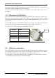
Contents 1 Introduction .............................................................................. 5 1.1 Overview ............................................................................. 5 1.2 Features .............................................................................. 5 1.3 Block diagram ..................................................................... 6 2 Indicators and connections ....................................................... 7 2.1 Overview ...........................
Introduction 1 Introduction 1.1 Overview With the IXXAT CAN-Repeater CAN-CR200, CAN-CR210/FO or CAN-CR220 you purchased a high-quality electronic component developed and manufactured according to the latest technological standards. The term "CAN-Repeater" is used in the following description to refer to the specific product. This manual is intended to familiarize you with the device. Please read this manual before beginning with the installation. 1.2 Features • Power supply range +9 V ...
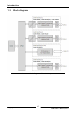
Introduction 1.3 Block diagram Picture 1-1 Block diagram of the CAN-Repeater Copyright IXXAT Automation GmbH 6 CAN-CR2xx - Manual, V2.
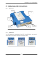
Indicators and connections 2 Indicators and connections 2.1 Overview CAN 3 Package lock Package lock LEDs Power CAN 2 CAN 1 Picture 2-1 Connectors and indicators of the CAN-CR200 2.2 Indicators The CAN-Repeater has a maximum of four LEDs. These LEDs show the communication status of the relevant interface or the device status. Picture 2-2 LEDs of the CAN-Repeater Copyright IXXAT Automation GmbH 7 CAN-CR2xx - Manual, V2.
Indicators and connections 2.2.1 Power-LED The Power LED P indicates the status of the power supply. If the LED is green, the power supply is working. If the LED is off, there is a problem with the power supply.
Indicators and connections 2.3 Connections 2.3.1 Power connector For the power connection of the CAN-Repeater, a screw terminal is used. For wiring, please ensure that the cross-sectional area of the cable is not less than 0.2mm². The maximum area is 2.5mm² for the connector. Pin No. 1 2 3 4 Signal +9 V bis +32 V DC 0V - Pin 1 Table 2-3 Pin allocation of the power connector The power connector is just plugged into the housing and can be removed with a screwdriver or similar tool. 2.3.
Indicators and connections the device on the DIN rail. The ground of the CAN bus interface is connected to earth via a 1 MΩ resistor and a 10 nF capacitor. For best noise immunity results, the shields of the CAN cables have to be grounded. 2.3.3 DIN rail bus and TBUS plug The CAN-CR200 and CAN-CR210/FO have a DIN rail bus. With this interface the device can be connected to other CAN-CR200 or CAN-CR210/FO devices.
Configuration 3 Configuration To operate the CAN-Repeater, no software installation is required. Before you can use the CAN-Repeater the internal DIP switches S301, S302, CAN1, CAN2 and CAN3 has to be set according to the CAN network configuration. In Picture 3-1 the positions of the DIP switches of the CAN-CR200 are shown. The DIP-switches of CAN-CR210/FO and CAN-CR220 are nearly at the same position.
Configuration 3.1 Configuration of the bus termination resistors For each CAN circuit a bus termination resistor can be activated /deactivated by a DIP switch. Always both positions should be set to ON / OFF. CAN1 OFF (deactivated) Default CAN2 OFF (deactivated) CAN3 ON (activated) Table 3-1 Configuration of the bus termination resistors The bus termination resistors should be activated if the CAN-Repeater is the first or the last device in the network.
Configuration 3.3 Configuration of the lock time With DIP switch S302 the lock time of the CAN-Repeater is defined. This time is used to avoid bit errors created by the device itself in a result of the signal propagation delay. Such an error could be a short dominant level inside of a recessive bit, which could cause bit errors at other CAN nodes (depending on the sampling point). The setting of the lock time has to be done according to the baudrate and the capacitive load of the network.
Installation 4 Installation To operate the CAN-Repeater, no software installation is required. Before you use the CAN-Repeater following points have to be paid attention: - configuration of the bus termination - configuration of the baudrate - configuration of the lock time More detailed information to these points can be found in chapter 3. 4.1 Mounting a single CAN-Repeater Prior to mounting the device it has to be assured, that the device is not connected to power.
Installation 4.2 Mounting with DIN rail bus support CAN-CR200 and CAN-CR210/FO support a DIN rail bus extension possibility. This feature gives you an easy possibility creating a star topology. ATTENTION: The usage of the DIN rail bus is specific for IXXAT devices. If another DIN rail bus is used, this one must not be connected to the IXXAT DIN rail bus.
Installation The interconnection of two TBUS plugs can be achieved by mounting the plugs and afterwards were moved together, as shown in Picture 4-3. Picture 4-3 Mounting of TBUS plugs Now the CAN-Repeater CAN-CR200 and/or CAN-CR210/FO can be mounted. The package of the CAN-CR200 and CAN-CR210/FO has an opening for the TBUS plug in the area of the DIN rail, see Picture 4-4 . While the devices are attached to the DIN rail, a correct mounting to the TBUS plug has to be observed.
Support Picture 4-5 Mounting an CAN-CR200 5 Support For more information on our products, FAQ lists and installation tips, please refer to the support area on our homepage (http://www.ixxat.com). There you will also find information on current product versions and available updates 6 Returning hardware If it is necessary to return hardware to us, please download the relevant RMA form from our homepage and follow the instructions on this form. Copyright IXXAT Automation GmbH 17 CAN-CR2xx - Manual, V2.
Appendix 7 Appendix 7.1 Technical specifications Power supply: Power consumption at 24 V: +9 V ... +32 V DC typical CAN-CR200 41 mA CAN-CR220 41 mA CAN-CR210/FO 62 mA CAN Transceiver: Texas Instruments SN65HVD251 maximum 100 mA 100 mA 100 mA Max.
Appendix 7.2 Accessories 7.2.1 CAN bus termination resistor IXXAT offers a bus terminal resistor as a feed through connector (order number 1.04.0075.03000). Picture 7-1 CAN bus terminal resistor 7.2.2 TBUS plug Interconnection with other IXXAT devices supporting the DIN rail bus (e.g. CANCR200 and/or CAN-CR210/FO) is possible by using the TBUS plug offered by IXXAT (order number 1.04.0073.00000). Picture 7-2 TBUS plug Copyright IXXAT Automation GmbH 19 CAN-CR2xx - Manual, V2.
Appendix 7.2.3 Glass fiber cable IXXAT offers cable assemblies for interconnection of two CAN-CR210/FO. Type FSMA length /m 2 5 order number 1.04.0003.01012 1.04.0003.01015 2 5 1.04.0003.01022 1.04.0003.01025 ST Picture Table 7-1 Glass fiber cable 7.3 EMI Hints The CAN-Repeater is a Class A device. This means, that it is tested and designed for industrial use and complies to this requirements. If the device is used in an office or living area, in extreme cases radio interferences could happen.
Appendix 7.4 Declaration of conformity IXXAT Automation hereby declares that the products: order number CAN-CR200 1.01.0067.44010 CAN-CR210/FO 1.01.0068.45010 1.01.0068.46010 CAN-CR220 1.01.0067.44400 1.01.0067.44300 do comply with the EC directives 2004/108/EC. Applied harmonized standards in particular: EN 55022:2006 + A1:2007 EN 55024:1998 + A1:2001 + A2:2003 22.08.2011, Dipl.-Ing. Christian Schlegel, Managing Director IXXAT Automation GmbH Leibnizstr.
Appendix 7.5 Note on disposal of used devices This product is subject to the ElektroG (electrical and electronic equipment act) and is to be disposed of in accordance with this act. The Terms of Sale and their supplements as well as further information on the disposal of used devices can be downloaded from www.ixxat.com. 7.6 FCC Compliance Declaration of conformity This device complies with Part 15 of the FCC Rules.