CANblue II Extended User Manual USER MANUAL 4.01.0126.20000 EN 3.
Important User Information Liability Every care has been taken in the preparation of this document. Please inform HMS Industrial Networks of any inaccuracies or omissions. The data and illustrations found in this document are not binding. We, HMS Industrial Networks, reserve the right to modify our products in line with our policy of continuous product development. The information in this document is subject to change without notice and should not be considered as a commitment by HMS Industrial Networks.
Table of Contents 1 2 Page User Guide ........................................................................................................................ 5 1.1 Target Audience.............................................................................................................5 1.2 Related Documents .......................................................................................................5 1.3 Document History .................................................................
Table of Contents 7.4.3 8 7.4.4 Setting the Transmitting Time .................................................................................. 23 7.4.5 Reset to Factory Settings ....................................................................................... 23 7.4.6 Changing the Bluetooth Passkey ............................................................................. 24 7.4.7 Visibility ................................................................................................
Table of Contents 14.2 Return Hardware .........................................................................................................54 15 Disposal........................................................................................................................... 54 A Regulatory Compliance............................................................................................... 55 A.1 EMC Compliance (CE) .............................................................................
This page intentionally left blank
User Guide 1 5 (62) User Guide Please read the manual carefully. Make sure you fully understand the manual before using the product. 1.1 Target Audience This manual addresses trained personnel who are familiar with CAN technology, Bluetooth® wireless technology and the applicable national standards. The contents of the manual must be made available to any person authorized to use or operate the product. 1.
User Guide 1.4 6 (62) Conventions Instructions and results are structured as follows: ► instruction 1 ► instruction 2 ➨ result 1 ➨ result 2 Lists are structured as follows: • item 1 • item 2 Bold typeface indicates interactive parts such as connectors and switches on the hardware, or menus and buttons in a graphical user interface. This font is used to indicate program code and other kinds of data input/output such as configuration scripts.
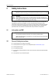
Safety Instructions 2 7 (62) Safety Instructions Risk of disturbances and interferences if used with WLAN at the same time! Bluetooth® wireless technology and WLAN both work with the frequency of 2.4 GHz. Caution This equipment emits RF energy in the ISM (Industrial, Scientific, Medical) band. Make sure that all medical devices used in proximity to this device meet appropriate susceptibility specifications for this type of RF energy. The CANblue II contains a small radio transmitter and receiver.
Scope of Delivery 2.3 8 (62) Bluetooth® Connection Make sure that the following conditions are met: • preferably unobstructed line of sight between the antennas of the devices • minimum distance of 50 cm between the devices (to avoid interference) • minimum distance of 10 m to WLAN recommended Data transmission rate depends on: 2.4 • distance between the communicating devices • obstacles between the devices • environment (texture of walls etc.
Product Description 4 9 (62) Product Description With the CANblue II multiple CAN networks can be connected wireless via Bluetooth® wireless technology. The CANblue II forwards from the CAN network received messages to the Bluetooth connection. The messages that are received via a Bluetooth connection are transmitted to the CAN network and other existing Bluetooth connections. The CANblue II provides an additional server. This connection can be used to configure the CANblue II.
Installation 5 10 (62) Installation Connection issues if the computer turns into sleep mode! Deactivate the sleep mode of the computer the CANblue II is connected to. In case of reconnecting problems see Errors and Troubleshooting, p. 26. 5.1 Installing the Software 5.1.1 Installing the Driver For the operation of the CANblue II as VCI PC interface for Windows the VCI driver is needed. ► 5.1.2 5.2 Install the VCI driver (see Installation Guide VCI Driver).
Installation 5.2.2 11 (62) External Antenna 1 Fig. 2 5.2.3 Connector for external antenna ► Screw the external antenna on connector (1). ► Use exclusively antennas that are approved by HMS Industrial Networks (by reason of radio certification). ► For further information about different antennas see www.ixxat.com. CAN Connector Pin Allocation of D-Sub 9 Connector Pin no. Signal 1 2 3 4 5 6 7 – 8 9 – – CANblue II User Manual CAN low GND – – – CAN high 4.01.0126.20000 EN 3.
Installation 5.3 12 (62) Installing the Virtual COM Port The CANblue II provides two virtual servers: Config and SPP. For the configuration of the CANblue II a Bluetooth-capable device that supports the serial port profile (SPP) must be connected to the Config server via a virtual COM port. Windows 7, 8 and 10 ► In Windows task bar right-click on the Bluetooth icon and select Add a device. ➨ All available devices are displayed. ➨ CANblue II devices are named IXXAT CANblue II ([MAC address]). Fig.
Installation 13 (62) ► Select Enter the device’s pairing code and click button Next. Fig. 5 ► Pairing code Enter the default pairing code 7388 and click button Next. ➨ Added device is displayed in window Devices and Printers. Some Bluetooth drivers do not ask for a pairing code. In this case pairing is possible without code. Determine the correct COM port: Fig.
Installation 14 (62) ➨ Fig. 7 ► Window CANblue II Properties is opened. CANblue II properties ➨ Two SPP server of the device are displayed. ➨ With the displayed COM port of Serial port (SPP) ‘Config’ (1) a connection to the CANblue II can be established. ➨ The COM port of Serial port (SPP) ‘SPP’ is reserved for a connection between two CANblue II devices. Make sure that both checkboxes of Serial port (SPP) ‘Config’ and of Serial port (SPP) ‘SPP’ are activated.
Configuration as PC Interface with VCI Driver 6 15 (62) Configuration as PC Interface with VCI Driver The CANblue II can be configured as a PC interface with the VCI driver for Windows. HMS recommends to reset the device to factory settings for optimal performance. Parallel usage with bridge mode is possible with reduced receive and transmit performance. Existing CAN filters are cleared in VCI mode and restored when the VCI mode is closed.
Configuration as Generic PC Interface or as Bridge 7 16 (62) Configuration as Generic PC Interface or as Bridge The CANblue II can be configured as Generic PC interface or as Bridge both with two different configuration tools. 7.1 Configuration Tools To configure the CANblue II a terminal program or the CANblueCon Configuration Tool can be used. Loading of existing configurations (txt- and bat-files) and the use of local commands is only possible with the CANblueCon Configuration Tool. 7.1.
Configuration as Generic PC Interface or as Bridge 17 (62) ► Make sure, that the virtual Config COM port is installed (see Installing the Virtual COM Port, p. 12). ► Start the command line. ► Enter the path to the CanBlueCon.exe. To load an existing configuration: ► In bridge configurations adjust the MAC address in the txt-file. ► Enter CanBlueCon.exe in the command line. ➨ Batch mode is started. ➨ Commands are read from the configuration file.
Configuration as Generic PC Interface or as Bridge 7.1.3 18 (62) Examples CANblue II command and CANblue II reply: >c can_init 1000 I OK: CAN_INIT Local command and local output: >#print CANblue Generic # CANblue Generic 7.2 Configuring an Interface The installed virtual Config COM port is used to configure the CANblue II to exchange data with a CAN network connected to the CANblue II.
Configuration as Generic PC Interface or as Bridge ► 19 (62) To transmit CAN messages to the CANblue II or into the connected CAN network, use ASCII or binary format (see Generic Mode Network and Device Communication, p. 28). ➨ Transmission format of CAN messages is automatically matched to the received format. Example Message ► To transmit a CAN data frame with the Standard identifier 7FF and the data bytes 1A 2B 3C 4D 5E 6F 70 to the CAN bus, use command M SD7 7FF 1A 2B 3C 4D 5E 6F 70.
Configuration as Generic PC Interface or as Bridge 7.3 20 (62) Configuring a Bridge Several Bluetooth devices can be connected as Master and Slave. Use only CANblue II devices with the same firmware version for a bridge. If CANblue II devices with new firmware version (V2.01.07 and higher) and CANblue II devices with an older firmware version are used in a Bridge contact IXXAT support for information about the compatibility.
Configuration as Generic PC Interface or as Bridge 21 (62) ► Save the configurations on both devices with the commands C CONFIG SAVE. ► To achieve the highest possible data rate between the devices, disconnect the Config connection to the computer. Since the connection is stored on both devices, devices reconnect automatically after turning off and on and resume to forward CAN messages. 7.3.
Configuration as Generic PC Interface or as Bridge 7.4 Settings in Generic Mode 7.4.1 Configuring the Filter 22 (62) Filtering of received messages is possible with the following criteria: • identifier • frame format (Extended, Standard) • frame type (data, remote) The filter works as a positive filter. CAN messages, with defined criteria in the filter list, that are received by the CAN controller are forwarded to the Bluetooth connection.
Configuration as Generic PC Interface or as Bridge 7.4.4 23 (62) Setting the Transmitting Time With the standard configuration, messages from the device are collected for up to 4 ms before transmission. The minimum time between the transmission of two consecutive transmission packets can be adjusted. ► Adjust the time between two transmission packets with command D BUFF_TIMEOUT. – Transmitting is possible before a Bluetooth SPP packet is filled completely.
Configuration as Generic PC Interface or as Bridge 7.4.6 24 (62) Changing the Bluetooth Passkey The default Bluetooth passkey is 7388. 7.4.7 ► Change the passkey with command D PASSKEY_SET. ► Use character strings with maximally 16 digits. Visibility It is possible to adjust if the CANblue II is visible and how long it stays visible after connecting to another device. ► 7.4.8 To specify the visibility, use command D VISIBILITY TIMEOUT.
Operation 25 (62) 8 Operation 8.1 Overview Mode CAN Fig. 11 8.2 LED array Indicators When the identity of device is requested, all LEDs are blinking. 8.2.1 8.2.2 8.2.3 8.
Errors and Troubleshooting 9 26 (62) Errors and Troubleshooting Terminal program replies E 99 Unknown Error to correctly entered commands. Commands are not typed in capital letters. ► In the terminal program enter the commands in capital letters. ► Before configuring the device, reset the device to factory settings or make sure that all filters are deleted or disabled. ► Reduce the traffic. ► Change the transmission type.
Errors and Troubleshooting CAN controller in bus off state If the controller is in bus off state in Bridge mode the messages in the Rx queue are transmitted via a Bluetooth connection to the connected CANblue. The messages in the Tx queue are transmitted via CAN when the CAN connection is restored. If the Tx queue is full, because of new messages received via the Bluetooth connection during the bus off, the oldest messages are overwritten (Tx queue can store maximally 256 messages).
PC Interface Driver Network and Device Communication 10 28 (62) PC Interface Driver Network and Device Communication For information about network and device communication with the VCI driver see Software Design Guides (.NET, C, C++) of the VCI. 11 Generic Mode Network and Device Communication To configure and transmit CAN messages via Bluetooth wireless technology an ASCII protocol is defined. To permit a better data rate a binary format is also available for the transmission of the messages.
Generic Mode Network and Device Communication 11.2 29 (62) CAN Commands The commands are used to control the CAN controller on the device and to modify the filter settings. Valid order of usage: 11.2.1 ► Initialize the CAN controller. ► Configure the filter. ► Start the CAN controller. ► Stop the CAN controller.
Generic Mode Network and Device Communication 30 (62) C CONFIG It is possible to save, load and show the configuration. C CONFIG Parameter Parameter Description operation Possible entries: SAVE: Saves the current configuration, can take several seconds. LOAD: Loads the existing configuration. SHOW: Shows the configuration.
Generic Mode Network and Device Communication 31 (62) C SEND_CAN_FRAMES Enables or disables the transmission of CAN messages in the directions the command comes from and sets the message format.
Generic Mode Network and Device Communication 11.2.2 32 (62) Initializing the CAN Controller C CAN_INIT Initializes the CAN controller with the specified baud rate. Exclusively CiA standard baud rates are supported (10, 20, 50, 100, 125, 250, 500, 800, 1000 kBaud). For custom baud rates see C CAN_INIT_CUSTOM. C CAN_INIT Parameter Parameter Description baud-rate Baud rate in kBaud. CAN controller is initialized with the specified baud rate.
Generic Mode Network and Device Communication 33 (62) C CAN_INIT_CUSTOM Initializes the CAN controller with custom baud rate. Parameters bt0 and bt1 correspond to the bus timing register of Phillips SJA 1000 CAN controller with a clock frequency of 16 MHz. Bit 7 of parameter bt1 is ignored, because the CANblue II CAN controller does not support different sample rates.
Generic Mode Network and Device Communication 34 (62) C FILTER_REMOVE Removes a filter entry from the filter list.
Generic Mode Network and Device Communication 35 (62) C FILTER_ENABLE Enables a Standard filter list or a Extended filter list. Messages are forwarded if the ID is found in the filter list. Filter lists for Standard IDs and for Extended IDs must be enabled separately.
Generic Mode Network and Device Communication 11.2.4 36 (62) Starting the CAN Controller C CAN_START Starts the CAN controller. Message format for transmitting CAN messages over the Bluetooth connection is set to ASCII mode. C CAN_START Possible Return Values Return Value Description I OK: CAN_START Function succeeded E 32 Error starting CAN Internal error while initializing the CAN controller. CAN controller not initialized. Try to initialize again.
Generic Mode Network and Device Communication 11.2.6 37 (62) Reset the CAN Controller C CAN_RESET Resets the CAN controller. C CAN_RESET Possible Return Values Return Value Description I OK: CAN_RESET Function succeeded CANblue II User Manual 4.01.0126.20000 EN 3.
Generic Mode Network and Device Communication 11.3 Device Commands 11.3.1 Requesting Device Information 38 (62) D VERSION Gets the firmware version of the CANblue II. D VERSION Possible Return Values Return Value Description I CANblue Generic — Bridge v2.01.07 I OK: VERSION Firmware version of the device D PROTOCOL Gets the ASCII protocol version. D PROTOCOL Possible Return Values Return Value Description I ASCII Extended Protocol v1.
Generic Mode Network and Device Communication 39 (62) D INFO Shows information about the configured Bluetooth connection settings and the Bluetooth connections. Additional information like connection quality, receive signal strength or transmission power is shown for each connection. D INFO Possible Return Values Return Value Description I Link-policy parameter: Bluetooth connection settings I Settingname: DEFAULT Name of configured connection settings (see D LINK_ POLICY, p.
Generic Mode Network and Device Communication 11.3.2 40 (62) MAC Commands for Connecting Devices D MAC_ADD Adds a MAC address to the connection list of a CANblue II. The Master device tries to establish a connection to the Bluetooth device with the added MAC address.
Generic Mode Network and Device Communication 41 (62) D MAC_CLEAR Removes all MAC addresses from the connection list of a CANblue II. An active connection or attempt to establish a connection is closed, when the command is called. This can cause a delayed response up to 5 seconds. D MAC_CLEAR Possible Return Values Return Value Description I OK: MAC_CLEAR Function succeeded D MAC_SCAN Starts a scan for other Bluetooth devices.
Generic Mode Network and Device Communication 11.3.3 42 (62) MAC Commands Security D MAC_MASTER_ADD Adds a MAC address or a MAC address range to the Master MAC address list. Slave devices then only accept Bluetooth connections from devices which MAC addresses are listed in the Master MAC address list. In the Master MAC address list 10 entries are available.
Generic Mode Network and Device Communication 43 (62) Possible Return Values Return Value Description I OK: MAC_SLAVE_ADD Function succeeded E 51 MAC-list is full E 52 Wrong MAC address Only 10 MAC address list entries are supported. Not possible to add another MAC address. MAC address is invalid. Valid MAC address consists of 12 digits. E 53 MAC address already exists MAC address is already used for a connection to a server. E 54 Invalid MAC Address range Address range is invalid.
Generic Mode Network and Device Communication 44 (62) Possible Return Values Return Value Description I OK: MAC_REMOVE Function succeeded E 52 Wrong MAC address MAC address is invalid or not in the Slave MAC address list. D MAC_MASTER_CLEAR Removes all MAC addresses from the Master MAC address list. After clearing the list, a Slave device accepts a Bluetooth connection from all devices.
Generic Mode Network and Device Communication 11.3.4 45 (62) Configuring the Device D CONFIG It is possible to save, load and show the configuration. D CONFIG Parameter Parameter Description operation SAVE: Saves the current configuration, can take several seconds. LOAD: Loads the existing configuration. SHOW: Shows the configuration.
Generic Mode Network and Device Communication 46 (62) D PASSKEY_SET Changes the Bluetooth passkey. D PASSKEY_SET Parameter Parameter Description key Bluetooth passkey, up to 16 digits, value: character string. In Bridge configurations use the same passkey for each device. Example D PASSKEY_SET 1234567890ABCD Possible Return Values Return Value Description I OK: PASSKEY_SET Function succeeded E 13 Wrong data length Invalid data length is received. Passkey is invalid.
Generic Mode Network and Device Communication 47 (62) D BUFF_TIMEOUT Sets the timeout for the transmitting buffer resp. the time between two consecutive Tx Bluetooth packets of the CANblue II. The timeout is applied to all Bluetooth connections of the device (for further information see Setting the Transmitting Time, p. 23).
Generic Mode Network and Device Communication 48 (62) D DEVICE_NAME_SET Changes the CANblue device name. The device name is transferred to the host device when a new configuration is established. Changes must be saved with command D CONFIG SAVE. Observe that changes are applied after a reboot of the device. D DEVICE_NAME_SET Parameter Parameter Description name Alphanumeric string, including special characters (but no blanks). Valid range is 10-16 characters.
Generic Mode Network and Device Communication 11.3.5 49 (62) Reset the Device D RESET The device transmits the response and resets itself. Any established Bluetooth connections are lost. D RESET Possible Return Values Return Value Description I OK: RESET Function succeeded D SETTINGS_DEFAULT The configuration is reset to the factory default settings. Stored configurations are deleted.
Generic Mode Network and Device Communication 11.4 50 (62) CAN Messages in ASCII format CAN Messages coded in ASCII format are called M-type messages. M-type messages are used to transmit CAN messages over a Bluetooth connection to another device. The receiving device forwards the message to all established Bluetooth connections and if the local CAN controller is started the message is transmitted to the CAN network.
Generic Mode Network and Device Communication 11.5 51 (62) CAN Messages in Binary Format CAN Messages coded in binary format are called X-type messages. Basic features of binary format: • allows faster transmission of CAN messages • data of the CAN message is transmitted uncoded in a binary value • fields are not separated by blanks • fields are without CR/LF characters X-type messages are used to transmit CAN messages over a Bluetooth connection to another device.
Generic Mode Network and Device Communication 11.6 52 (62) Error Messages Error message Description E 1 Unknown command Invalid command or message type is received. E 2 Wrong parameter Parameter of a command is invalid. E 3 Unsupported command Received command is not supported. E 4 Unsupported parameter Parameter of a command is not supported. E 11 Wrong message type Invalid message type is received (valid: Standard or Extended).
Technical Data 12 53 (62) Technical Data Bluetooth® qualification v4.0 (Bluetooth® classic) Output power 11 dBm, internal antenna 13 dBm, external antenna Bluetooth® output frequency 2.402 to 2.480 GHz, ISM band CAN transceiver Max. number of CAN bus nodes Power supply Texas Instruments SN65HVD251 120 9 to 30 V DC Power consumption Typ. 50 mA at 12 V, max. 100 mA at 12 V Dimensions Weight 81 x 66 x 26 mm Approx.
Support/Return Hardware 14 54 (62) Support/Return Hardware Observe the following information in the support area on www.ixxat.com: 14.1 14.2 15 • information about products • FAQ lists • installation notes • updated product versions • updates Support ► For problems or support with the product request support at www.ixxat.com/support. ► If required use support phone contacts on www.ixxat.com. Return Hardware ► Fill in the form for warranty claims and repair on www.ixxat.com.
Appendix A: Regulatory Compliance A 55 (62) Regulatory Compliance The IXXAT CANblue II with external antenna port is for OEM integrations only. The end-user product will be professionally installed in such a manner that only the authorized antennas are used. A list of authorized antennas is available from www.ixxat.com. A.1 EMC Compliance (CE) The product is in compliance with the Electromagnetic Compatibility Directive. More information and the Declaration of Conformity is found at www.ixxat.com. A.
Appendix B: Disposal and recycling 56 (62) This equipment has been tested and found to comply with the limits for a Class B digital device, pursuant to Part 15 of the FCC rules. These limits are designed to provide reasonable protection against harmful interference in a residential installation. This equipment generates, uses and can radiate radio frequency energy and, if not installed and used in accordance with the instructions, may cause harmful interference to radio communications.
Appendix C: Measurements C 57 (62) Measurements CANblue II User Manual 4.01.0126.20000 EN 3.
Appendix D: Configuration Examples 58 (62) D Configuration Examples D.1 Example 1: Connecting a CAN Network With a Computer The example shows how an installed virtual COM port can be used to configure the CANblue II to exchange data with a CAN network connected to the CANblue II. CAN bus 1 CAN connector CANblue II Bluetooth connection (SPP-Server) Master Slave Config Bluetooth connection Bluetooth PC Fig.
Appendix D: Configuration Examples ► Save the configuration with command C CONFIG SAVE. ► Start the CAN controller with command C CAN_START. ➨ ► ► If the CAN controller receives a message from the CAN network that matches one of the filters, the message is transmitted on the Bluetooth connection in ASCII format. To transmit CAN messages to the CANblue II or into the connected CAN network use ASCII format or binary format (see Generic Mode Network and Device Communication, p. 28). ➨ D.
Appendix D: Configuration Examples 60 (62) Slave Device ► Make sure that the virtual COM port is installed and that a connection is established. ► Make sure that the software package (CANblue_II_Generic_Setup.exe) is installed. ► Start the terminal program or the CANblue Configuration Tool (CANblueCon.exe). ► Reset the device to factory settings with command D SETTINGS_DEFAULT. ➨ CAN controller is automatically initialized to 1000 kBaud (preset in factory settings).
Appendix D: Configuration Examples D.3 61 (62) Example 3: Configuring a Bridge Chain Configuring a bridge chain is possible because every Slave can serve as Master for another Slave.
last page © 2018 HMS Industrial Networks Box 4126 300 04 Halmstad, Sweden info@hms.se 4.01.0126.20000 EN 3.