
Manual
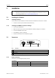
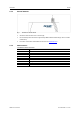
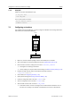
Table Of Contents
- 1 User Guide
- 2 Safety Instructions
- 3 Scope of Delivery
- 4 Product Description
- 5 Installation
- 6 Configuration as PC Interface with VCI Driver
- 7 Configuration as Generic PC Interface or as Bridge
- 8 Operation
- 9 Errors and Troubleshooting
- 10 PC Interface with VCI Driver Network and Device Communication
- 11 Generic Mode Network and Device Communication
- 12 Technical Data
- 13 Default Settings
- 14 Support/Return Hardware
- 15 Disposal
- A Regulatory Compliance
- B Disposal and recycling
- C Measurements
- D Configuration Examples

Installation 11 (64)
5.2.2 External Antenna
Fig. 2 Connector for external antenna
► Screw the external antenna on connector (1).
► Use exclusively antennas that are approved by HMS Industrial Networks (by reason of radio
certification).
► For further information about different antennas see www.ixxat.com.
5.2.3 CAN Connector
Pin Allocation of D-Sub 9 Connector
Pin no. Signal
1
–
2
CAN low
3 GND
4
–
5
–
6
–
7
CAN high
8
–
9
–
CANblue II User Manual
4.01.0126.20000 3.4 en-US