CAN FD Repeater CAN-CR100, CAN-CR110/FO, CAN-CR120/HV, CAN-CR300 USER MANUAL 4.01.0210.20000 1.
Important User Information Disclaimer The information in this document is for informational purposes only. Please inform HMS Industrial Networks of any inaccuracies or omissions found in this document. HMS Industrial Networks disclaims any responsibility or liability for any errors that may appear in this document. HMS Industrial Networks reserves the right to modify its products in line with its policy of continuous product development.
Table of Contents 1 2 Page User Guide ........................................................................................................................... 3 1.1 Target Audience...............................................................................................................3 1.2 Document History ............................................................................................................3 1.3 Trademark Information ...................................................
10 Disposal.............................................................................................................................. 13 A Regulatory Compliance ..................................................................................................... 15 A.1 EMC Compliance (CE) ..................................................................................................... 15 A.2 FCC Compliance Statement ................................................................................
User Guide 1 3 (18) User Guide Please read the manual carefully. Make sure you fully understand the manual before using the product. 1.1 Target Audience This manual addresses trained personnel who are familiar with CAN, CAN FD and the applicable standards. The contents of the manual must be made available to any person authorized to use or operate the product. 1.2 1.3 Document History Version Date Description 1.0 February 2018 First release 1.1 February 2018 Minor corrections 1.
User Guide 1.4 4 (18) Conventions Instructions and results are structured as follows: ► instruction 1 ► instruction 2 → result 1 → result 2 Lists are structured as follows: • item 1 • item 2 Bold typeface indicates interactive parts such as connectors and switches on the hardware, or menus and buttons in a graphical user interface. This font is used to indicate program code and other kinds of data input/output such as configuration scripts.
Safety Instructions 5 (18) 2 Safety Instructions 2.1 Information on EMC Risk of interference to radio and television if used in office or home environment! Make sure, that DIN rail is connected to the ground. Use exclusively included accessories. Use exclusively shielded cables. Make sure, that the shield of the CAN cable is connected. If necessary, enlarge distance between source of interference (e.g. motors, frequency inverter) or drain of interference and device to avoid interference. 2.2 2.
Product Description 6 (18) 4 Product Description 4.
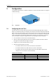
Configuration 5 7 (18) Configuration To operate the CAN repeater no software installation is required. The CAN repeater is configured via DIP switches (1). 1 Fig. 1 5.1 DIP switches Configuring the Lock Time The CAN transceiver transmits data and receives these transmitted data again after a certain delay, the so-called loop delay.
Configuration 5.2 8 (18) Extending the Recessive Bit Due to the internal structure the CAN transceiver shortens recessive bits on the network, and thus dominant bits are extended. At high bit rates this might cause errors. To extend the recessive bits may improve the error rate, as the bits then are closer to their nominal value on the network. If the recessive bits are extended with the DIP switches, the extension is made independently of the bit rate, also at low bit rates.
Installation 9 (18) 6 Installation 6.1 Mounting the Device 1 2 Fig. 2 6.2 Mounting on DIN rail ► Make sure that the lock time is configured (see Configuration, p. 7). ► Make sure, that the device is not connected to power supply. ► Hook the device onto the upper lip of the rail and push downwards (1). ► Push the device towards the rail until it snaps into place (2). Connectors 1 2 3 4 5 Fig.
Installation 6.2.1 10 (18) Power Connector Pin Allocation 6.2.2 Pin no. Signal 1 +9 V to +36 V DC 2 3 0V — 4 — CAN Connector Pin Allocation Pin no. Signal 1 CAN high 2 CAN low 3 CAN GND 4 Shield If a D-Sub 9 connector is used, observe the following pin allocation of the D-Sub 9 connector. Pin no. 1 Signal — 2 CAN low 3 4 CAN GND — 5 — 6 — 7 8 CAN high — 9 — The shield of the CAN connector is connected to the ground via a 10 nF capacitor.
Operation 11 (18) 7 Operation 7.1 LEDs PWR CAN 1 2 3 4 Fig. 4 LED array LEDs PWR 2/3/4 do not have any function. The LEDs CAN 3/4 are activated only with CAN-CR300. 7.1.1 Power LED Power LED PWR 1 indicates the status of the power supply. 7.1.
Technical Data 8 12 (18) Technical Data Weight Approx.
13 (18) Support/Return Hardware 9 Support/Return Hardware 9.1 Support 9.2 10 ► For problems or support with the product request support at www.ixxat.com/support. ► If required use support phone contacts on www.ixxat.com. Return Hardware ► Fill in the form for warranty claims and repair on www.ixxat.com/support/product-returns. ► Print out the Product Return Number (PRN resp. RMA). ► Pack product in a physically- and ESD-safe way, use original packaging if possible. ► Enclose PRN number.
This page intentionally left blank
Appendix A: Regulatory Compliance 15 (18) A Regulatory Compliance A.1 EMC Compliance (CE) The product is in compliance with the Electromagnetic Compatibility Directive. More information and the Declaration of Conformity is found at www.ixxat.com. A.2 FCC Compliance Statement This device complies with Part 15 of the FCC Rules. Operation is subject to the following two conditions: • This device may not cause harmful interference.
Appendix A: Regulatory Compliance A.3 16 (18) RoHs Directive The product is in compliance with the RoHs Directive 2002/95/EC (Restriction of the use of certain hazardous substances in electrical and electronic equipment). A.4 Disposal and recycling You must dispose of this product properly according to local laws and regulations. Because this product contains electronic components, it must be disposed of separately from household waste.
This page intentionally left blank
last page © 2020 HMS Industrial Networks Box 4126 300 04 Halmstad, Sweden info@hms.se 4.01.0210.20000 1.