
Manual
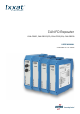
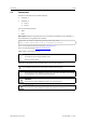
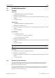
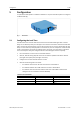
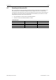
Table Of Contents

Configuration 7 (18)
5 Configuration
To operate the CAN repeater no software installation is required. The CAN repeater is configured
via DIP switches (1).
Fig. 1 DIP switches
5.1 Configuring the Lock Time
The CAN transceiver transmits data and receives these transmitted data again after a certain
delay, the so-called loop delay. For example, if the transceiver transmits a dominant bit and after
that a recessive bit, the transceiver only sees the recessive bit in its receive output after the loop
delay. The size of the loop delay depends on several factors, like for example the number of CAN
nodes in the network. The higher the capacity load is, the higher is the loop delay. To avoid bit
errors caused by this delay, the configured lock time must be higher then the loop delay.
► Use a screwdriver or similar tool to set the DIP switches.
► Observe, that the setting depends on the bit rate and the capacitive load of the network
(the higher the capacity load, the higher the value).
► Configure the lock time with DIP switches 1 and 2.
► Observe the following reference values:
– for networks with less than 32 nodes the lock time is about 200 ns
– for networks between 32 and 64 nodes the lock time is about 400 ns
– for networks with more than 64 nodes the lock time is about 800 ns and with this
setting the bit rate is limited to maximal 500 kbit/s
Valid Lock Time Combinations
DIP switch 1 DIP switch 2 Lock time
Off Off 200 ns (default)
On
Off
400 ns
Off
On 800 ns
On On 1600 ns
1
CAN FD Repeater User Manual
4.01.0210.20000 1.4 en-US