
Datasheet


IXD_604
12 www.clare.com R02
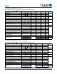
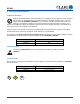
5.4.3 Tape & Reel Information for SI and SIA Packages
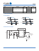
5.4.4 PI (8-Pin DIP)
NOTES:
1. A
0
& B
0
measured at 0.3mm above base of pocket.
2. 10 pitches cumulative tol. ± 0.2mm
3. ( ) Reference dimensions only.
4. Unless otherwise specified, all dimensions in millimeters.
K
0
=2.30 ± 0.10
B
0
=5.20 ± 0.10
R0.50 TYP
8.00 ± 0.10
2.00 ± 0.10
4.00 ± 0.10 See Note #2
12.00 ± 0.30
5.50 ± 0.10
1.75 ± 0.10
∅1.50 (MIN)
∅1.55 ± 0.05
1.80 ± 0.10
(3.40)
0.30 ± 0.05
(70º)
A
0
=6.40 ± 0.10
(4.70)
(1.20)
A
A
B
B
SECTION A-A
SECTION B-B
Embossment
Embossed Carrier
To p Co ver
Tape Thickness
0.102 MAX.
(0.004 MAX.)
330.2 DIA.
(13.00 DIA.)
Dimensions
mm MIN / mm MAX
(inches MIN / inches MAX)
NOTE: Molded package conforms to JEDEC standard configuration
MS-001 variation BA.
PC Board Pattern
7.62 / 10.92
(0.300 / 0.430)
7.62 BSC
(0.300 BSC)
0.20 / 0.38
(0.008 / 0.015)
7.37 / 8.26
(0.290 / 0.325)
0.38 / 0.58
(0.015 / 0.023)
1.14 / 1.65
(0.045 / 0.065)
0.38 / 1.02
(0.015 / 0.040)
3.05 / 3.81
(0.120 / 0.150)
3.43 / 4.70
(0.135 / 0.185)
3.18 / 3.81
(0.125 / 0.150)
8-0.900 DIA.
(8-0.035 DIA.)
7.50
(0.295)
2.540
(0.100)
9.02 / 10.16
(0.355 / 0.400)
6.10 / 6.86
(0.240 / 0.270)
2.540 BSC
(0.100 BSC)
1.40
(0.055)