
Datasheet


IXD_609
R02 www.clare.com 13
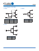
5.4.5 PI (8-Pin DIP)
5.4.6 CI (5-Pin TO-220)
Dimensions
mm MIN / mm MAX
(inches MIN / inches MAX)
NOTE: Molded package conforms to JEDEC standard configuration
MS-001 variation BA.
PC Board Pattern
7.62 / 10.92
(0.300 / 0.430)
7.62 BSC
(0.300 BSC)
0.20 / 0.38
(0.008 / 0.015)
7.37 / 8.26
(0.290 / 0.325)
0.38 / 0.58
(0.015 / 0.023)
1.14 / 1.65
(0.045 / 0.065)
0.38 / 1.02
(0.015 / 0.040)
3.05 / 3.81
(0.120 / 0.150)
3.43 / 4.70
(0.135 / 0.185)
3.18 / 3.81
(0.125 / 0.150)
8-0.900 DIA.
(8-0.035 DIA.)
7.50
(0.295)
2.540
(0.100)
9.02 / 10.16
(0.355 / 0.400)
6.10 / 6.86
(0.240 / 0.270)
2.540 BSC
(0.100 BSC)
1.40
(0.055)
NOTES:
1. This drawing will meet all dimensions requirement of
JEDEC outlines TS-001AA and 5-lead version TO-220AB.
2. Mounting hole diameter: 3.53 / 3.96 (0.139 / 0.156)
3. The metal tab is connected to pin 3 (GND).
Finished Hole Diameter = 1.45mm (0.057 in.)
Recommended Hole Pattern
1.70mm (0.067 in.)
25.27 / 26.54
(0.995 / 1.045)
11.94 / 12.95
(0.470 / 0.510)
14.73 / 15.75
(0.580 / 0.620)
9.91 / 10.54
(0.390 / 0.415)
1.70 BSC
(0.067 BSC)
0.64 / 1.02
(0.025 / 0.040)
8.64 / 9.40
(0.340 / 0.370)
4.32 / 4.83
(0.170 / 0.190)
1.14 / 1.40
(0.045 / 0.055)
0.38 / 0.64
(0.015 / 0.025)
2.29 / 2.92
(0.090 / 0.115)
DIMENSIONS
mm MIN / mm MAX
(inches MIN / inches / MAX)
12.387
(0.487)
6.299
(0.248)
7.823
(0.308)
12.70 / 14.73
(0.50 / 0.58)
7.620
(0.300)
6.502
(0.256)
1 2 3 4 5
3