
Datasheet
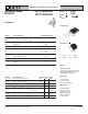


IXYS Reserves the Right to Change Limits, Test Conditions, and Dimensions.
IXTH16N20D2
IXTT16N20D2
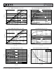
Fig. 7. Normalized R
DS(on)
vs. Junction Temperature
0.8
0.9
1.0
1.1
1.2
1.3
1.4
1.5
1.6
-50 -25 0 25 50 75 100 125 150
T
J
- Degrees Centigrade
R
DS(on)
- Normalized
V
GS
= 0V
I
D
= 8A
Fig. 8. R
DS(on)
Normalized to I
D
= 8A Value
vs. Drain Current
0.2
0.6
1.0
1.4
1.8
2.2
2.6
0 5 10 15 20 25 30 35 40
I
D
- Amperes
R
DS(on)
- Normalized
V
GS
= 0V
5V
- - - -
T
J
= 125ºC
T
J
= 25ºC
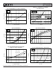
Fig. 9. Input Admittance
0
10
20
30
40
50
-4.0 -3.5 -3.0 -2.5 -2.0 -1.5 -1.0 -0.5 0.0 0.5 1.0
V
GS
- Volts
I
D
- Amperes
T
J
= 125ºC
25ºC
- 40ºC
V
DS
= 20V
Fig. 10. Transconductance
0
5
10
15
20
25
30
0 5 10 15 20 25 30 35 40 45 50
I
D
- Amperes
g
f s
- Siemens
T
J
= - 40ºC, 25ºC, 125ºC
V
DS
= 20V
Fig. 12. Forward Voltage Drop of Intrinsic Diode
0
5
10
15
20
25
30
0.3 0.4 0.5 0.6 0.7 0.8 0.9
V
SD
- Volts
I
S
- Amperes
T
J
= 125ºC
V
GS
= -10V
T
J
= 25ºC
Fig. 11. Normalized Breakdown and Threshold
Voltages vs. Junction Temperature
0.8
0.9
1.0
1.1
1.2
1.3
-50 -25 0 25 50 75 100 125 150
T
J
- Degrees Centigrade
BV / V
GS(off)
V
GS(off)
@ V
DS
= 25V
BV
DSX
@ V
GS
= - 5V