
Datasheet


LCA110
www.clare.com
5
R10
Manufacturing Information
Soldering
For proper assembly, the component must be
processed in accordance with the current revision
of IPC/JEDEC standard J-STD-020. Failure to
follow the recommended guidelines may cause
permanent damage to the device resulting in impaired
performance and/or a reduced lifetime expectancy.
Recommended soldering processes are limited to
260ºC component body temperature for 10 seconds.
Washing
Clare does not recommend ultrasonic cleaning or the
use of chlorinated solvents.
e
3
RoHS
2002/95/EC
Top Cover
Tape Thickness
0.102 MAX.
(0.004 MAX.)
K
1
= 3.80
(0.150)
W = 16.30 MAX
(0.642 MAX)
B
0
= 10.10
(0.398)
A
0
= 10.10
(0.398)
P = 12.00
(0.472)
330.2 DIA.
(13.00 DIA.)
K
0
= 4.90
(0.193)
0.254 TYP
(0.010 TYP)
7.620 ± 0.254
(0.300 ± 0.010)
3.302 ± 0.051
(0.130 ± 0.002)
9.144 ± 0.508
(0.360 ± 0.020)
8.382 ± 0.381
(0.330 ± 0.015)
6.350 ± 0.127
(0.250 ± 0.005)
2.540 ± 0.127
(0.100 ± 0.005)
7.620 ± 0.254
(0.300 ± 0.010)
3.302 ± 0.051
(0.130 ± 0.002)
0.254 ± 0.0127
(0.010 ± 0.0005)
0.635 ± 0.127
(0.025 ± 0.005)
4.445 ± 0.127
(0.175 ± 0.005)
8.382 ± 0.381
(0.330 ± 0.015)
2.540 ± 0.127
(0.100 ± 0.005)
6.350 ± 0.127
(0.250 ± 0.005)
0.457 ± 0.076
(0.018 ± 0.003)
9.525 ± 0.254
(0.375 ± 0.010)
7.239 TYP
(0.285 TYP)
Tape and Reel Packaging for Surface Mount Package
Top Cover
Tape
Embossment
Embossment Carrier
User Direction of Feed
1 6
PC Board Pattern
(Top View)
2.540 ± 0.127
(0.100 ± 0.005)
8.305 ± 0.127
(0.327 ± 0.005)
1.499 ± 0.127
(0.059 ± 0.005)
1.905 ± 0.127
(0.075 ± 0.005)
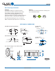
6-Pin DIP Through Hole (Standard)
Dimensions:
mm
(inches)
PC Board Pattern
(Top View)
6.350 ± 0.127
(0.250 ± 0.005)
2.540 ± 0.127
(0.100 ± 0.005)
7.620 ± 0.127
(0.300 ± 0.005)
5.080 ± 0.127
(0.200 ± 0.005)
6-0.800 DIA.
(6-0.031 DIA.)
6-Pin Surface Mount ("S" Suffix)
MECHANICAL DIMENSIONS