
Datasheet


© 2002 IXYS All rights reserved
1 - 3
CS 20
Symbol Test Conditions Maximum Ratings
I
T(RMS)
T
VJ
= T
VJM
30 A
I
T(AV)M
T
case
= 85°C; 180° sine 19 A
I
TSM
T
VJ
= 45°C; t = 10 ms (50 Hz), sine 200 A
V
R
= 0 V t = 8.3 ms (60 Hz), sine 215 A
T
VJ
= T
VJM
t = 10 ms (50 Hz), sine 180 A
V
R
= 0 V t = 8.3 ms (60 Hz), sine 195 A
I²t T
VJ
= 45°C t = 10 ms (50 Hz), sine 200 A
2
s
V
R
= 0 V t = 8.3 ms (60 Hz), sine 195 A
2
s
T
VJ
= T
VJM
t = 10 ms (50 Hz), sine 162 A
2
s
V
R
= 0 V t = 8.3 ms (60 Hz), sine 158 A
2
s
(di/dt)
cr
T
VJ
= T
VJM
repetitive, I
T
= 40 A 150 A/ms
f = 50 Hz, t
P
=200 ms
V
D
= 2/3 V
DRM
I
G
= 0.3 A non repetitive, I
T
= I
T(AV)M
500 A/ms
di
G
/dt = 0.3 A/ms
(dv/dt)
cr
T
VJ
= T
VJM
;V
DR
= 2/3 V
DRM
1000 V/ms
R
GK
= ¥; method 1 (linear voltage rise)
P
GM
T
VJ
= T
VJM
t
P
= 30 ms10W
I
T
= I
T(AV)M
t
P
= 300 ms5W
P
GAV
0.5 W
V
RGM
10 V
T
VJ
-40...+125 °C
T
VJM
125 °C
T
stg
-40...+125 °C
M
d
Mounting torque M3 0.8...1.2 Nm
Weight 6g
Features
●
Thyristor for line frequency
●
International standard package
JEDEC TO-247
●
Planar passivated chip
●
Long-term stability of blocking
currents and voltages
●
Epoxy meets UL 94V-0
Applications
●
Motor control
●
Power converter
●
AC power controller
●
Switch-mode and resonant mode
power supplies
●
Light and temperature control
Advantages
●
Easy to mount with 1 screw
(isolated mounting screw hole)
●
Space and weight savings
●
Simple mounting
●
Improved temperature and power
cycling
Data according to IEC 60747
IXYS reserves the right to change limits, test conditions and dimensions
Phase Control Thyristor V
RRM
= 1200-1600 V
I
T(RMS)
= 30 A
I
T(AV)M
= 19 A
V
RSM
V
RRM
Type
V
DSM
V
DRM
VV
1200 1200 CS 20-12io1
1400 1400 CS 20-14io1
1600 1600 CS 20-16io1
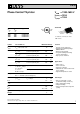
A
C
G
A
G
C
TO-247 AD
C = Cathode, A = Anode, G = Gate
TAB = Anode
(TAB)
235