
Datasheet

© 2000 IXYS All rights reserved
2 - 2
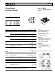
VUO 35
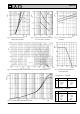
Fig. 6 Transient thermal impedance per diode
Fig. 1 Forward current versus Fig. 2 Surge overload current per diode Fig. 3 I
2
t versus time (1-10 ms)
voltage drop per diode I
FSM
: Crest value. t: duration per diode
Fig. 4 Power dissipation versus direct output current and ambient temperature Fig. 5 Maximum forward current at
case temperature
Constants for Z
thJC
calculation:
iR
thi
(K/W) t
i
(s)
1 0.194 0.024
2 0.556 0.07
3 0.45 3.25
43.0 9.3
Constants for Z
thJK
calculation:
iR
thi
(K/W) t
i
(s)
1 0.194 0.024
2 0.556 0.07
3 0.45 3.25
43.0 9.3
5 0.6 28.0
I
2
t