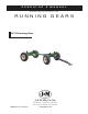
O P E R A T O R ’ S M A N U A L and Set-Up Instructions for RUNNING GEARS 1074 Running Gear J. & M. Mfg. Co., Inc. P.O. Box 547 Ft. Recovery, OH 45846 Ph: (419) 375-2376 Fax: (419) 375-2708 JMMAN0101 (Rev. 03/10/05) www.jm-inc.
TO THE DEALER: Read manual instructions and safety rules. Make sure all items on the Dealer’s Pre-Delivery and Delivery Check Lists in the Operator’s Manual are completed before releasing equipment to the owner. The dealer must complete the Warranty Registration Card attached to the front inside cover of this manual and return to J. & M. Mfg. Co., Inc. at the address indicated on the card. Warranty claims will be denied if the Warranty Registration Card has not been completed and returned.
10 TON RUNNING GEAR SPECIFICATIONS SPECIFICATIONS Capacity Weight (with tires)* Width (c/c of tire) Spindle Size Spring Balanced Tongue Ground Height (to top of axle) Rocking Bolster Tongue, Adjustable Quick Hitch Adjustable Center Pole Wheels - 6 bolt 10 Ton 960 lbs 74” 2” diameter Standard 27” Optional Standard Standard 15 x 8 or 15 x 10 *Weighed with 12.
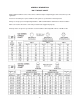
GENERAL INFORMATION BOLT TORQUE CHART Always tighten hardware to these values unless a different torque or tightening procedure is listed for a specific application. Fasteners must always be replaced with the same grade as specified in the manual parts list. Always use the proper tool for tightening hardware: SAE for SAE hardware and Metric for metric hardware. Make sure fastener threads are clean and you start thread engagement properly.
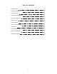
TABLE OF CONTENTS INTRODUCTION 2 EXPRESS WARRANTY 2 SPECIFICATIONS 3 GENERAL INFORMATION 3 BOLT TORQUE CHART 4 SAFETY RULES 6 SAFETY SIGNS 7 SET-UP INSTRUCTIONS 7 OPERATION 8 ROUTINE MAINTENANCE 8 PARTS LIST/DIAGRAM 9 SERVICE RECORDS 10 5
SAFETY RULES ATTENTION! BECOME ALERT! YOUR SAFETY IS INVOLVED! Safety is a primary concern in the design and manufacture of our products. Unfortunately, our efforts to provide safe equipment can be erased by an operator’s single careless act. In addition, hazard control and accident prevention are dependent upon the awareness, concern, judgement, and proper training of personnel involved in the operation, transport, maintenance and storage of equipment.
50-16 OWNER’S MANUAL SAFETY SIGNS ATTENTION! BECOME ALERT! YOUR SAFETY IS INVOLVED! Replace Immediately If Damaged or Missing! IMPORTANT: Install new safety signs if the old signs are destroyed, lost, painted over or cannot be read. When parts are replaced that have safety signs, make sure you install a new sign with each new part. New signs are available from the manufacturer or your authorized dealer. Ref.
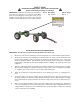
750-16 OWNER’S MANUAL OPERATING INSTRUCTION / MAINTENANCE BE CERTAIN THAT ALL POWER IS SHUT OFF BEFORE SERVICING EQUIPMENT.
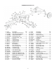
RUNNING GEAR PARTS LIST # 1 2 3 4 5 6 7 8 9 10 11 12 13 14L 14R 15L 15R 16 17L 17R 18 19 20 21 22 Part # OT-610NS IT-610NS TL-610NS SS-615NS LS-610 CP-112 ST-610 TB-610 HN-114 KP-610 HW-10 BB-58 SB-58 TRE-78L TRE-78R HN-78L HN-78R TR-22316 SA-10L SA-10R EB-2 CP-212 MB-2 FA-10 RA-10 Description Adj. Tongue Outer Weldment Adj. Tongue Inner Weldment Tongue Latch Weldment Small Spring in Latch Latch Pivot Shaft, 1" Dia.
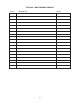
SERVICE / MAINTENANCE RECORD DATE DESCRIPTION NOTES 10