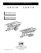
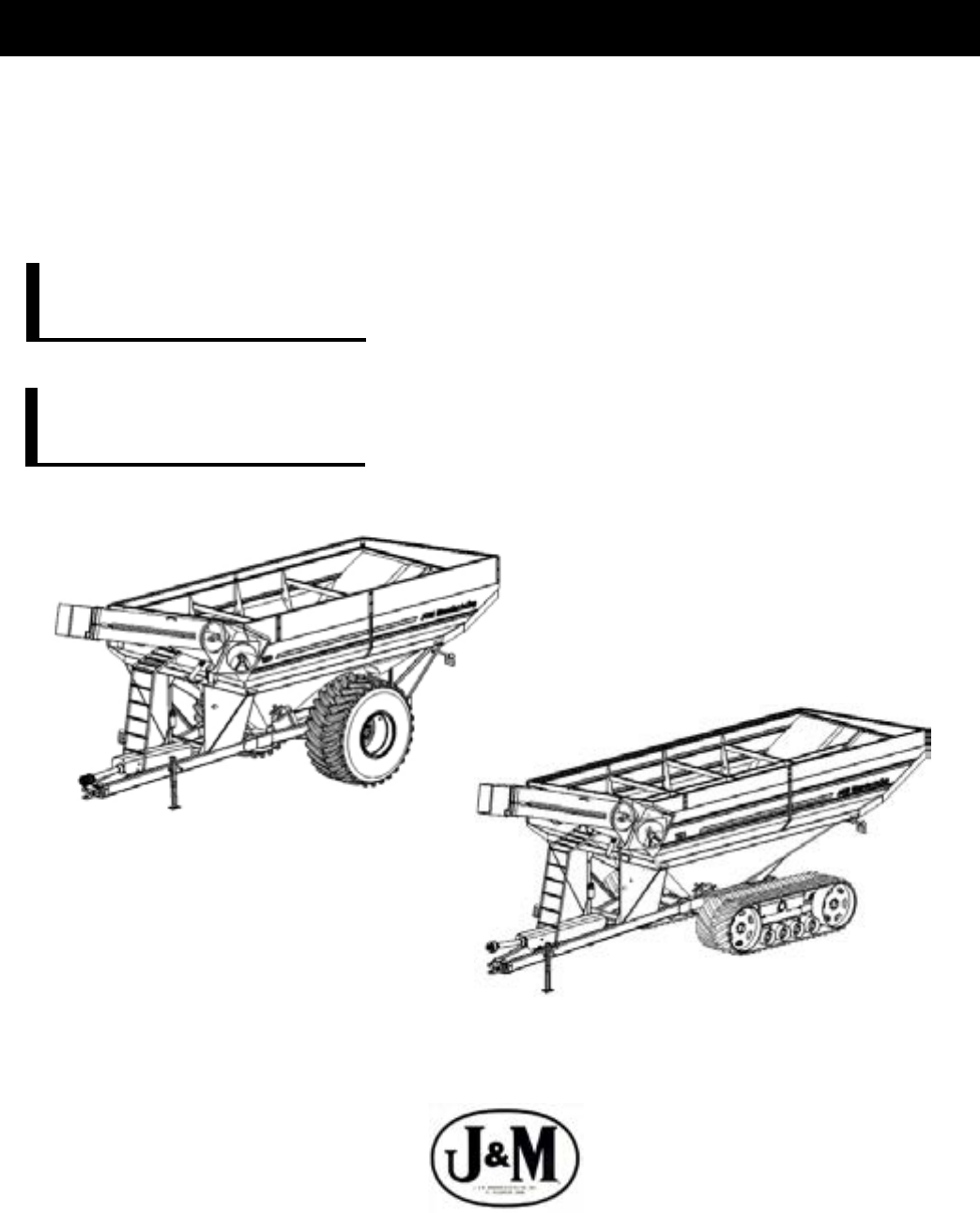
O P E R A T O R ’ S G R A I N M A N U A L C A R T S 1326-22S Grain Cart 1326-22T Grain Cart J. & M. Mfg. Co., Inc. P.O. Box 547 Ft. Recovery, OH 45846 Ph: (419) 375-2376 Fax: (419) 375-2708 JMMAN0101 (Rev. 12/21/11) www.jm-inc.
TO THE DEALER: Read manual instructions and safety rules. Make sure all items on the Dealer’s Pre-Delivery and Delivery Check Lists in the Operator’s Manual are completed before releasing equipment to the owner. The dealer must complete the Warranty Registration Card attached to the front inside cover of this manual and return to J. & M. Mfg. Co., Inc. at the address indicated on the card. Warranty claims will be denied if the Warranty Registration Card has not been completed and returned.
Most Avaliable Phone Number:__________________________________________________________ 2i
PLEASE CUT AND RETURN 2ii
1326-22S GRAIN CART SPECIFICATIONS SPECIFICATIONS Capacity 1,325 bushels Auger, one vertical 22” diameter Wheels 44x32 Hubs 10 bolt Spindles 6” diameter Weight (approx.
GENERAL INFORMATION BOLT TORQUE CHART Always tighten hardware to these values unless a different torque or tightening procedure is listed for a specific application. Fasteners must always be replaced with the same grade as specified in the manual parts list. Always use the proper tool for tightening hardware: SAE for SAE hardware and Metric for metric hardware. Make sure fastener threads are clean and you start thread engagement properly.
TABLE OF CONTENTS INTRODUCTION 2 EXPRESS WARRANTY 2 SPECIFICATIONS 3 GENERAL INFORMATION 3 BOLT TORQUE CHART 4 SAFETY RULES 6 SAFETY SIGNS 7 INITIAL OPERATION 8 OPERATION 9-11 ROUTINE MAINTENANCE 11 TROUBLE SHOOTING 12 SERVICE 13-14 STORAGE 14 REMOVING FROM STORAGE 14 PARTS LISTS/DIAGRAMS 15-20 WEIGH SCALE INSTALLATION INSTRUCTIONS 21-23 ROLL TARP INSTALLATION 24-29 AUTO LOG INSTALLATION
SAFETY RULES ATTENTION! BECOME ALERT! YOUR SAFETY IS INVOLVED! Safety is a primary concern in the design and manufacture of our products. Unfortunately, our efforts to provide safe equipment can be erased by an operator’s single careless act. In addition, hazard control and accident prevention are dependent upon the awareness, concern, judgement, and proper training of personnel involved in the operation, transport, maintenance and storage of equipment.
750-16 OWNER’S MANUAL SAFETY SIGNS ATTENTION! BECOME ALERT! YOUR SAFETY IS INVOLVED! Replace Immediately If Damaged or Missing! IMPORTANT: Install new safety signs if the old signs are destroyed, lost, painted over or cannot be read. When parts are replaced that have safety signs, make sure you install a new sign with each new part. New signs are available from the manufacturer or your authorized dealer. 3 1 7 2 Not Shown 4 17 5 16 14 7 Ref.
INITIAL OPERATION/MAINTENANCE BE CERTAIN THAT ALL POWER IS SHUT OFF BEFORE SERVICING THE GRAIN CART.
OPERATING INSTRUCTIONS BE CERTAIN THAT ALL POWER IS SHUT OFF WHEN HOOKING UP TO TRACTOR OR CONNECTING HYDRAULIC LINES TO TRACTOR. Preparing the Grain Cart for Use (see tractor recommendation for grain cart model below): Model 1326-22 Grain Carts require a 4WD tractor. IMPORTANT: Do NOT pull loaded grain cart on highway. For incidental highway travel, observe the section below. Tow Loads Safely Stopping distance increases with speed and weight of towed loads, and on slopes.
IMPORTANT: 1) Hookup grain cart to tractor using a good quality hitch pin. Attach a safety chain (not included as standard equipment) to the tractor and around the A-frame of the cart as shown. Make sure the grain cart hitch properly matches the hitch of the tractor. Use a single prong (spade) grain cart hitch with a tractor double prong (clevis) hitch. Use a double prong (clevis) grain cart hitch with a single prong (spade) tractor hitch.
LUBRICATION SERVICE SCHEDULE IMPORTANT: Your Grain Cart has grease fittings at all critical points. These should be serviced before the cart is put into operation. BE CERTAIN THAT ALL POWER IS SHUT OFF BEFORE SERVICING THE GRAIN CART. Hitch: There is a grease fitting located on the pivot shaft of the swivel hitch. PTO & Drive Line: The grease fittings on the PTO should be serviced after every 8 hours of use.
TROUBLE SHOOTING MAKE SURE THAT ALL POWER IS SHUT OFF BEFORE SERVICING THE GRAIN CART. MAINTENANCE AND REPAIR SERVICE WORK TO BE PERFORMED BY QUALIFIED SERVICEMEN ONLY. Trouble... Possible Cause ... Possible Remedy ...
ADJUSTING THE SLIP CLUTCH After the first hour of operation, the slip-disc clutch should be checked for overheating. After this first check, the slip-disc clutch should be checked weekly or anytime there is excessive slippage of the friction discs. The slipdisc clutch should be checked for moisture, which could cause corrosion on the drive plates.
REMOVING DIRT FROM RESTRICTERS ON HYDRAULIC CYLINDER MAKE SURE THAT ALL POWER IS SHUT OFF AND THE UPPER AUGER TUBE IS IN THE DOWN POSITION BEFORE REMOVING THE RESTRICTERS. Remove restricters from 90 degree street elbow on hydraulic cylinder. Remove dirt from fitting to allow hydraulic oil to flow freely through the restricter. Reattach the restricter to the street elbow. Use teflon sealant tape or equivalent on the threads of the restricter before reattaching.
REPAIR PARTS LIST AND DIAGRAMS When performing maintenance work, wear sturdy, rough-soled work shoes and protective equipment for eyes, hair, hands, hearing and head. Follow Operator’s Manual instructions to ensure safe and proper maintenance and repair. Your local, authorized dealer can supply genuine replacement parts. Substitute parts may not meet original equipment specifications and may be dangerous. BE CERTAIN THAT ALL POWER IS SHUT OFF BEFORE PERFORMING ANY MAINTENANCE OR REPAIR WORK.
POWER TAKE-OFF SHAFT # 1 2 3 4 5 6 7 8 9 10 11 12 13 14 15 16 17 18 19 20 21 22 23 24 25 26 27 Part # 28428 18130 18133 00243 18210 30710 90010 00271 18134 84033 19121 19122 27820 00452 16490 15107 16489 00085 18428 14022 18016 19019 19018 00502 18453 19014 19115 Description Complete Collar Yoke C15 Cross Journal Set Outer Yoke Roll Pin for Outer Tube Bush with Grease Nipple Complete Outer Tube Inner Tube Roll Pin for Inner Tube Inner Yoke Complete Slip Clutch Retain Collar for Outer Tube Retain Collar fo
DRIVE LINE ASSEMBLY # 1 2 3 4 5 6 7 8 9 Part # 252288 UCF-20928 38112 SS-3812 SS-1212 DS-134193 GDS-134193 3S-DUJ CK-44R Description U-Joint (drive shaft to gearbox) 1 3/4” Flange Bearing, 4 hole 3/8” x 1 1/2” Half Moon Key 3/8” x 1/2” Set Screw 1/2”-20 x 1/2” Set Screw Drive Shaft, 1 3/4” x 193” Guard for Drive Shaft (incl.
HYDRAULIC CYLINDER ASSEMBLY (To Raise and Lower the Upper Auger) # Part # 1 JD324 2 JD324-1 3 ICR4 4 38SE90 5 5602-6-6 6 PC-37 7 BJW-114 8 HN-114 9 1404-062 10 HH-1421 11 HH-14218 12 HH-14206 13 RG-1 Description 3” x 24” Hyd. Cylinder Seal Kit for 3” x 24” Hyd Cylinder 1” x 4” Pin with Hair Pin 3/8” Street Elbow 90 3/8” Street Tee Pilot Check Valve Ball Joint Weldment with 1 1/4” Hex Nuts 1 1/4” Hex Jam Nut Orifice Restrictor (.
HYDRAULIC DRIVEN FLOW CONTROL SPOUT 9 4/5 14 12/13 8 1 6 10/11 3 2 # 1 Part # Description FSH-22 Flow Control Spout Housing FSH-22S Slider Flow Control Spout Hosing 2 HP-22 Hinge HP-22S Slider Hinge 3 BP-22 Baffle Plate BP-22S Slider Baffle Plate 4 HC-FCS Hyd.
GRAIN CART LIGHT KIT # 1 2 3 4 5 5 6 7 8 9 10 11 12 13 14 15 16 16 16 17 Part # 8WH-7PC LE-1B WH-1 EL-A1 RL-R1L RL-R1R MS-1 FLW-1 FLDLT-1 RD-1A RD-1R RD-1O SMV-1 GR-1 7-WCE AL-1 RL-1A RL-1LH RL-1RH NC-1MS Description Main Wiring Harness with 7-Prong Connector End Light Enhancer (108060) Wiring Harness (Rear Half) Extendable Amber Light Assembly (Left/Right) Rear Red Light, Left Rear Red Light, Right Mercury Switch Field Light Wire Field Light Reflective Amber Decal Reflective Red Decal Reflective Orange
Installation of Scale System for Grain Carts Equipped with Tracks, Dual Wheels or Single Wheel HITCH ASSEMBLY 1. Remove the 2 1/2” x 13 1/4” shaft from the swivel hitch by unbolting the 1” x 5 1/2” Grade 5 bolt and locknut that attaches the swivel hitch and the 1” x 4 1/2” Grade 5 bolt and locknut that attaches the rear collar. 2. Remove the eight 3/4” x 3” Grade 8 Bolts from the Hitch Spool Plate Support located on the front of the A-Frame. 3.
Installation of Scale System for Grain Carts Equipped with Tracks, Dual Wheels or Single Wheel MOUNTING THE JUNCTION BOX 1. 2. Using the Junction Box as a template, mark and drill holes on the inside face of the front left side leg of the Run Wires grain cart. The Junction Box should be positioned from Left Weigh Bars approximately 23” above the top of the A-Frame.
Installation of Scale System for Grain Carts Equipped with Tracks, Dual Wheels or Single Wheel NOTE: When inserting the hitch weigh bar, be sure that the TOP decal on the spindle is facing upward. When Inserting the remaining four weigh bars, be sure that the TOP decal on the spindle is facing downward. Failure to correctly align the weigh bar and spindles in the upright position will cause the scale system to read with greater inaccuracy.
Grain Cart Roll Tarp Parts List and Set Up Instructions 19 16 9 11 21 4 14 3 23 10 8 20 12 13 2 18 1 5 17 Rear View of Grain Cart PARTS LIST # Part # 1 SO-2 2 CUJ-1N 2 CUJ-1NL 2 CUJ-1EL 3 150RRT 3 164RRT 3 174RRT 3 198RRT 3 230RRT 3 1050RRT 3 1325RRT 4 144TT 4 158TT 4 168TT 4 192TT 4 224TT 4 1050TT 4 1325TT 5 TL-144 5 TL-158 5 TL-168 Description Qty Stand-Off 2 Crank with Splined U-joint (525) 1 Crank with Splined U-joint (620 thru 875) 1 Crank with Splined U-joint (100 thru 132
Grain Cart Roll Tarp Parts List and Set Up Instructions # Part # 15 316C-150 15 316C-164 15 316C-174 15 316C-198 15 316C-1050 15 316C-240 15 316C-1325 16 TSB-1 17 ABCH-1 17 ABCH-1L 17 ABCH-1EL 18 CH-1N 19 525CT 19 620T 19 750CT 19 875T 19 1050T 19 1075T-1822 19 1325T 20 516EB 21 TNR1 22 SRTSPR1 23 SUJ-1 24 316CC 25 SRRLLR1 26 SPRLLR2 27 SPRPS2 28 SSRASP2 29 SRTSP1 30 SRSPS1 31 HLN-14 32 1434-HHMB 33 14215-HBP 34 1458-HB 35 1412-HB 36 SFN-14 37 141-HB 38 1434STS 39 1412STS 40 HLN-38 41 SFN-
Roll Tarps for Grain Carts SET-UP INSTRUCTIONS Installing the Lock Panel (Drip Edge) 1 Center the lock panel from the front to the rear of the cart on the off auger side of the cart. Make sure that the lock panel is flush to the inside of the sideboard. Holes may already be pre-drilled for the installation or may need drilled out with a 1/4” drill bit. Use a pair of vise grips to temporarily hold the lock panel to the off auger side of the cart.
Roll Tarps for Grain Carts SET-UP INSTRUCTIONS (Continued) Installing the Tarp Bows 4 Lay all three bows in the cart with the ends on the sideboareds. Then install two 1/4”-20 x 3/4” serrated flange hex bolts and two 1/4”-20 serrated flange hex nuts on each end of all bows. Line the bows up with the holes in the sideboards and not the drip edge if the holes are different. If drip edge holes are different, they will need to be drilled.
Roll Tarps for Grain Carts SET-UP INSTRUCTIONS (Continued) Tarp Stand-Offs Installing the Tarp Stand-Offs each tarp standoff at each end of the 7 Install grain cart wall on the off auger side with two 1/4” x 1 1/2 self tapping bolts. Place it about 2” down from the drip edge along side of the corner brace. Riveting the Canvas Tarp to the Square Tubing the 1”x1” 14ga x 192” long square tube into 8 Insert the sleeve on the Canvas Tarp that is on the opposite side of the Stiffening Patch.
Roll Tarps for Grain Carts SET-UP INSTRUCTIONS (Continued) Attaching the Canvas Tarp to the Roll Pipe 10 On the opposite side of the canvas tarp, slide the 1” schedule roll pipe into the remainng sleeve on the canvas tarp with the spline end towards the rear of the cart. Line up the spool on the roll pipe with the spring return on the front of the grain cart.
DIGI-STAR Autolog for Grain Carts SET-UP INSTRUCTIONS 1) 2) 3) 4) 5) 7) 8) To complete the installation of the Digi-star Autolog system on a grain cart drive shaft: First remove the drive shaft cover guard located on the backside of the middle bearing on the drive shaft (detail 1). The drive shaft cover tube (detail 5) can now be cut back six inches from the end closest to the front of the cart.
SERVICE / MAINTENANCE RECORD DATE DESCRIPTION NOTES 31