
Manual


23
NOTE: When inserting the hitch weigh bar, be sure that the TOP decal on the spindle is facing upward. When Inserting
the remaining four weigh bars, be sure that the TOP decal on the spindle is facing downward. Failure to correctly align
the weigh bar and spindles in the upright position will cause the scale system to read with greater inaccuracy.
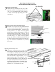
Installation of Scale System
for Grain Carts Equipped with Tracks, Dual Wheels or Single Wheel
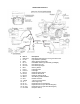
Single Wheel or Track
Grain Cart Layout Diagram
Scale packages for grain carts equipped with Tracks and Single Wheels feature a
ve point system that includes ve hitch weigh bars only. A ve point junction box is
used for all scale systems on grain carts equipped with tracks and Single Wheels.
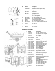
Walking Tandem Dual
Wheel Layout Diagram
Scale packages for grain carts equipped with Walking Tandem Dual Wheels
feature a ve point weigh system that includes four weigh spindles and one hitch
weigh bar. A weigh system with a ve point junction box is used on all scale
systems for grain carts equipped with walking tandem dual wheels.
Front Legs of
Grain Cart
Weigh Spindles (Insert Adapter Tubing Pipe)
(typical each side)
Battery Box
Indicator Box
Junction Box
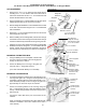
Secure Weigh Bar Weldment to rear
A-frame hitch plate using 4 3/4” x
3” bolts with heavy lockwashers and
nuts. Bolt hitch to weigh bar and
secure to rear Weigh Bar Weldment
using existing 1” x 4 1/2” Grade 5
Bolt with nut.
Run Weigh Spindle wires out of
grommet and through the wire chan-
nel accross to the Junction Box.
Run Weigh Spindle wires out of
grommet to the Junction Box.
Run Hitch Weigh Bar Wire out of tubing frame at
front grommet and connect to Junction Box.
Secure Weigh Bar Weldment to rear
A-frame hitch plate using 4 3/4” x
3” bolts with heavy lockwashers and
nuts. Bolt hitch to weigh bar and
secure to rear Weigh Bar Weldment
using existing 1” x 4 1/2” Grade 5
Bolt with nut.
Battery Box
Indicator Box
Junction Box
Weigh Bars
(typical each side)
Models 1000 and Lower
Front Legs of
Grain Cart
Insert Weigh Spindle wires through
adjacent grommet and run inside
tubing to grommet shown.
(typical each side)
Run Hitch Weigh Bar Wire out of tubing frame at
front grommet and connect to Junction Box.
Run Weigh bar
wires out of grom-
met and through
the wire channel
accross to the Junc-
tion Box.
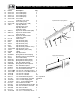
Insert Weigh Bar wires through
adjacent grommets and run inside
tubing to grommet shown.
(typical each side)
Run Weigh Bar wires
out of grommet to the
Junction Box.
Insert Weigh Bar wires through
adjacent grommets and run inside
tubing to grommet shown.
(typical each side)
Run Weigh Bar wires out of tubing
frame at front grommet and through
cross tube as shown. Then connect
the wires to the Junction Box