
User Manual


11
Mount the Front Angle Bracket to the front diagonal brace of the gravity box using two 1/4” x 3/4” self-tapping
screws.
Slide the Main Wiring Harness 7-Prong Connector End through the Front Angle Bracket towards the hitch. The
black and white wire and 7-Wire Nose Box on the Main Wiring Harness should run to the rear of the gravity box
through either the steel runner or conduit.
Place black Plastic Grommet around the circular cut-out of the Front Angle Bracket.
Secure the 7-Wire Nose Box and Angle Bracket of the Main Wiring Harness back along the runner to the door
opening of the gravity box for the optional door light. If the gravity box does not have the optional door light, wrap
black and white wire and place inside steel runner of gravity box for storage.
Drill two holes in rear leg of gravity box as shown and secure Light Enhancer on inside face of rear leg using two
1/8” x 1” Hex Bolts and Nuts. (Note: The Light Enhancer should be mounted so the two sets of wire connec-
tors hang from the enhancer box.)
Connect the Main Wiring Harness to the Light Enhancer.
Connect Light Wiring Harness to the Light Enhancer and the red and amber lights on the rear leg above. To
connect the opposite side red and amber lights, run the Light Wiring Harness along the gravity box bracing
connecting the steel runners. Secure the Light Wiring Harness using the three Wire Loom Clamps and Self
Tapping Screws.
Place one amber reflective decal at each extreme end of both sides and front of the gravity box as shown.
Place one red and one orange reflective decal at each extreme end of the rear of the gravity box as shown. The
red decal should be placed above the orange decal.
NOTE: The Front and Rear Angle Brackets are not required on Models 440SD, 540SD, 680SD and 760SD.
The Flood Light is optional on Models 250-7S and 385SD.
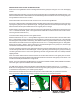
GRAVITY BOX LIGHT KIT SET UP INSTRUCTIONS:
For J&M Gravity Wagons, Mount the Operator’s Manual Storage Container using two 1/4” x 1” Carriage
Bolts and 1/4” Flange Nuts to the inside face of the front leg of the gravity wagon as shown (see Figures 1, 2
or 3 below that corresponds to your model of gravity wagon).
Read and Understand all the information in the Operator’s Manual BEFORE you operate this machine.
Keep the Operator’s Manual in the Storage Container and reference the manual as required.
Model 250-7S Model 385SD Models 440SD, 540SD,
680SD or 760SD
Mount
Here
Mount
Here
Slide the bolt head of one 1/4” x 1” Carriage Bolt through each of the two slots located on the rear side of each
light. The bolt pattern should correspond to the hole pattern on the rear leg of the gravity box. Place the light
wire through the hole provided on the rear leg, then slide the bolts through the two holes on the rear leg. Set the
Wire Guard on the inside face of the rear leg and secure to the 1/4” x 1” Carriage Bolt using the 1/4” Flange Nut.
Repeat for each light. (NOTE: When mounting the red and amber lights to the gravity box, the Red Light
should be mounted above the Amber Light on each side.)