
Manual

Combine Grain Tank Set-Up Instructions
for Case IH 1660, 1666, 2166, 2366, 1680, 1688, 2188 & 2388 Series Combines
Lanyards and
Lynch Pins
shown below
are typical on
Front, Rear
and Side
Panels
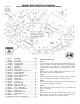
Assembly Instructions
Step 1:
Lay out the frame halves, Angle Iron Rail and Flat Rail on the
top of the combine as shown. Attach Angle Iron and Flat Rails
to frame halves using eight 3/8” x 1” Flange Bolts. (NOTE:
The Flat Rail has a small angle iron welded to the rear side.)
Step 2:
Drill holes to secure to combine tank using four 5/16” x 1 1/2”
Flange Bolts and four 5/16” Flange Nuts.
Step 3:
Drill Holes and fasten Left Frame Plate to combine using two
5/16” x 5/8” Flange Bolts and two 5/16” Flange Nuts.
Step 4:
Layout corner panels as shown and attach using eight 3/8” x
4 1/2” Bolts and eight 3/8” Lock Nuts.
Step 5:
Attach side panels to frame using four 1/4” x 4 1/2” Bolts and
four 1/4” Lock Nuts
Step 6:
Attach front and rear panels to frame using four 1/4” x 4 1/2”
Bolts and four 1/4” Lock Nuts. NOTE: The panel with the
Danger Decal should be used as the rear panel.
# Part # Description Qty
1 CIH-CP1 Corner Panel 2
2 CIH-CP2 Corner Panel 2
3 CIH-FRP Front/Rear Panel 2
4 CIH-LRP Left/Right Panel 2
5 CIH-LF Left Frame 1
6 CIH-RF Right Frame 1
7F CIH-AR-F Angle Iron Rail 1
7R CIH-AR-R Flat Rail (with welded angle iron) 1
8 IW-71212 Inspection Window 4
9 62095-7 Window Molding 4
10 CIH-SMB Sensor Mounting Bracket 1
11 CIH-EW1 Extension Wire 1
12 CTE-PP Plastic Plug 8
13 CTE-PL Plastic Lanyard 16
14 CTE-LP Lynch Pin 16
15 FN-516 5/16" Flange Nut 8
16 HB-38412 3/8" x 4 1/2" Bolt 8
17 6MM-475 6MM Bolt x 4 3/4" (8.8) 8
18 FB-381 3/8" x 1" Flange Bolt 10
19 FB-51658 5/16" x 5/8" Flange Bolt 4
20 LN-38 3/8" Lock Nut 8
21 6MM-NLN 6MM Nylon Lock Nut 8
22 FN-38 3/8" Flange Nut 2
23 CTE-SS1 Step 1
24 FB-516112 5/16" x 1 1/2" Flange Bolt 4