MODEL 66-80 VIBRATORY DRIVER/EXTRACTOR OPERATING AND MAINTENANCE MANUAL J&M 66-80 VIBRATORY PILE DRIVER/EXTRACTOR WITH MODEL 800 POWER PACK J&M Foundation Equipment 1201 Banksville Road — Pittsburgh, PA 15216 Phone: 412.341.8190 — Fax: 412.341.
MODEL 66-80 VIBRATORY DRIVER/EXTRACTOR
MODEL 66-80 VIBRATORY DRIVER/EXTRACTOR PREFACE This manual was prepared to acquaint the owner, operator and serviceman with the operation and maintenance of the vibratory driver/extractor. We suggest that this manual be carefully studied before operating or undertaking any maintenance work on the unit. This manual is organized into two major sections.
MODEL 66-80 VIBRATORY DRIVER/EXTRACTOR
MODEL 66-80 VIBRATORY DRIVER/EXTRACTOR WARRANTY J&M FOUNDATION EQUIPMENT (J&M) STANDARD WARRANTY J&M warrants new products sold by it to be free from defects in material or workmanship for a period of 1 year after date of delivery to the first user and subject to the following conditions: J&M's obligation and liability under this WARRANTY is expressly limited to repairing or replacing, at J&M's option, any parts which appear to J&M, upon inspection, to have been defective in material or workmanship.
MODEL 66-80 VIBRATORY DRIVER/EXTRACTOR TABLE OF CONTENTS OPERATING INSTRUCTIONS I. II. GENERAL DESCRIPTION PAGE A. B. C. D. E. F. G. I- 1 I- 2 I- 2 I- 2 I- 2 I- 2 I- 3 PREPARATION FOR OPERATION A. B. C. D. E. F. G. III. General Safety Precautions Rigging of Vibrator Connection of Hydraulic Clamp Connection of Hydraulic Hoses Bleeding Hydraulic Clamp Hoses Filling Vibrator Pressure Hose II- 1 II- 1 II- 2 II- 2 II- 3 II- 5 II- 5 OPERATING INSTRUCTIONS A. B. C. D. E. F. G. IV.
MODEL 66-80 VIBRATORY DRIVER/EXTRACTOR TABLE OF CONTENTS OPERATING INSTRUCTIONS (CONTINUED) V. HYDRAULIC CIRCUITRY PAGE A. B. C. V- 1 V- 1 V- 3 V- 4 V- 5 D. VI. Hydraulic Clamp Vibrator Drive Motor Other Hydraulic Schematic Hydraulic Components List ELECTRICAL CIRCUITRY A. B. C. D. E. F. G. H. I.
MODEL 66-80 VIBRATORY DRIVER/EXTRACTOR
MODEL 66-80 VIBRATORY DRIVER/EXTRACTOR I. GENERAL DESCRIPTION A. GENERAL The J&M Model 66 is a variable-frequency vibratory pile driver/extractor designed to drive and extract sheet, pipe, timber and concrete piles, caissons, H-beams, Ibeams and wide-flange beams. The Model 66 operates in a frequency range of 800 to 1600 vibrations per minute to provide maximum pile penetration rates in a wide variety of soils.
MODEL 66-80 VIBRATORY DRIVER/EXTRACTOR I. GENERAL DESCRIPTION B. VIBRATOR The vibrator consists of two major components; The vibration case and the vibration suppressor. The vibration case contains six eccentric weights which rotate in a vertical plane to create vibration. The eccentric weights are driven by two hydraulic motors. The vibration suppressor contains a minimum of 24 rubber elastomers to isolate the vibration case from the crane line.
MODEL 66-80 VIBRATORY DRIVER/EXTRACTOR I. GENERAL DESCRIPTION G. SPECIFICATIONS 1. Constant improvement and engineering progress make it necessary that we reserve the right to make specification changes without notice. L W HH H 66 T MODEL 196 CLAMP BODY (SHOWN) 2. MODEL 66-80 VIBRATOR (with hydraulic clamp) Type ........................................................ Hydraulic Eccentric Moment ............... 6600 In-lbs (50.7kg-M) Frequency. .......................................
MODEL 66-80 VIBRATORY DRIVER/EXTRACTOR II. PREPARATION FOR OPERATION A. GENERAL When unloading and unpacking the vibratory driver, use extreme care. For your protection, make a thorough inspection of the unit immediately on delivery. In case of any damage or shortage, notify the transit agent at once and have the delivering carrier make a notation on the freight bill. B. SAFETY PRECAUTIONS Safety is basically common sense.
MODEL 66-80 VIBRATORY DRIVER/EXTRACTOR II. PREPARATION FOR OPERATION B. SAFETY PRECAUTIONS (CONTINUED) 18. When servicing batteries, do not smoke or use open flames in the vicinity. Batteries generate explosive gas during charging. There must be proper ventilation when charging batteries. 19. When filling fuel tank, do not smoke or use open flame in the vicinity. 20. If abnormal equipment operation is observed, discontinue use immediately and correct the problem.
MODEL 66-80 VIBRATORY DRIVER/EXTRACTOR II. PREPARATION FOR OPERATION B. SAFETY PRECAUTIONS (CONTINUED) 38. Never clamp vibrator to pile and disconnect the crane line. Loss of hydraulic pressure could cause vibrator to fall. Lay vibrator down when not in use. 39. When extracting piles, always attach a safety line between pile and crane hook. 40. When extracting piles, check crane load/radius tables to be sure crane capacity is adequate for maximum allowable extraction pull. 41.
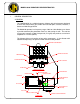
MODEL 66-80 VIBRATORY DRIVER/EXTRACTOR II. PREPARATION FOR OPERATION E. CONNECTION OF HYDRAULIC HOSES 1. Connection of hoses at power unit. a. The vibrator and hydraulic clamp are connected to the power unit by five hydraulic hoses (Fig. 1). CAUTION: The power unit must be shut down during connection of the hydraulic hoses. b. The hoses connect to the power unit with quick-disconnect couplers. The hose couplers are arranged to insure correct connections at the power unit. See the diagram (Fig.
MODEL 66-80 VIBRATORY DRIVER/EXTRACTOR II. PREPARATION FOR OPERATION E. CONNECTION OF HYDRAULIC HOSES (CONTINUED) 2. Connection of hoses at vibrator. a. The vibrator is usually shipped with the hoses attached to the vibrator. If the hoses have been shipped separately, they must be connected in the field. Fig. 1 on the previous page shows the correct arrangement of the 5 hoses connecting the power unit to the vibrator.
MODEL 66-80 VIBRATORY DRIVER/EXTRACTOR II. PREPARATION FOR OPERATION F.BLEEDING HYDRAULIC CLAMP HOSES 1. When the vibrator and hydraulic clamp are shipped with all hoses attached (between vibrator and clamp and five main hoses connected to the vibrator), the hoses are usually full of oil and may be used immediately. However, if any of the clamp hoses are connected at the job site or if air is present in hoses, they must be bled prior to operation. 2. Read SECTION III - OPERATING INSTRUCTIONS. 3.
MODEL 66-80 VIBRATORY DRIVER/EXTRACTOR III. OPERATING INSTRUCTIONS CONTROL PANEL WITH REMOTE-CONTROL PENDANT e f p v a FORWARD BRAKE CLOSE OPEN HYD. FLUID TEMP. ENGINE OIL b i FILTER CLOG ENGINE WATER HYD. FLUID TEMP. HIGH LOW LEVEL ENGINE HYD. FLUID OVER SPEED ENG OIL PRESS. TEMP HIGH OPEN c s CLOSE l CLAMP ON STOP t RETURN PRESS. LOW TACHOMETER START ENG WATER TEMP.
MODEL 66-80 VIBRATORY DRIVER/EXTRACTOR III. OPERATING INSTRUCTIONS A. COMPLETION OF SET-UP AND MAINTENANCE 1. Complete all preparation as described in Section II. 2. Read Section IV - MAINTENANCE AND ADJUSTMENTS and perform any required maintenance. B. CONTROL PANEL 1. The control box (Fig. 1, page III-1) at the side of the power pack contains the controls and gages for the diesel engine and the vibrator and the OPERATION AND MAINTENANCE INSTRUCTIONS. 2.
MODEL 66-80 VIBRATORY DRIVER/EXTRACTOR III. OPERATING INSTRUCTIONS B. CONTROL PANEL (CONTINUED) 3. Engine Overspeed shutdown indicator - comes on if engine has been shut down automatically due to the engine being run at excessively high RPM. 4. Filter Clogged shutdown indicator - comes on if engine has been shut down automatically due to the hydraulic oil return filter being clogged. 5.
MODEL 66-80 VIBRATORY DRIVER/EXTRACTOR III. OPERATING INSTRUCTIONS C. STARTING AND WARMING UP ENGINE 1. Before starting the engine, read the CATERPILLAR OPERATION GUIDE carefully. Follow the engine starting, operating and maintenance procedures in that manual. 2. The diesel engine should not be started if the temperature of the hydraulic oil is below 0°F (-18°C). If ambient temperatures below 0°F (-18°C) are anticipated, an immersion heater for the hydraulic oil is available. Consult J&M for details. 3.
MODEL 66-80 VIBRATORY DRIVER/EXTRACTOR III. OPERATING INSTRUCTIONS D. WARMING HYDRAULIC OIL (CONTINUED) 3. When the engine is warmed up and hydraulic oil temperature is at least 60°F (16°C), full speed operation may begin. 4. The hydraulic oil temperature should be monitored with the Hydraulic Temperature Oil Switch Gage. Oil temperature should never exceed 160°F (71°C). The engine will automatically shut down if oil temperature exceeds 160°F (71°C).
MODEL 66-80 VIBRATORY DRIVER/EXTRACTOR III. OPERATING INSTRUCTIONS E. OPERATION OF REMOTE-CONTROL PENDANT (CONTINUED) c.To Stop Vibration: Press the STOP button. The vibrator will stop vibration in a few seconds. If the STOP button does not stop the vibrator, pressing the Emergency Stop button will shut down the Power Unit and the vibrator will stop. d. To unclamp from pile. Turn the CLAMP switch to OPEN to release the hydraulic clamp so that the vibrator can be removed from the pile.
MODEL 66-80 VIBRATORY DRIVER/EXTRACTOR III. OPERATING INSTRUCTIONS F.CHANGING FREQUENCY 1. In order to provide maximum flexibility in achieving optimum pile penetration and extraction rates, the frequency of the vibratory driver is adjustable. 2. The frequency can be varied from 800 to 1600 vibrations per minute by changing engine speed. Engine speed is changed with the ENGINE THROTTLE on the control panel or with the remote electric throttle (FAST / SLOW) switch on the pendant.
MODEL 66-80 VIBRATORY DRIVER/EXTRACTOR IV. MAINTENANCE AND ADJUSTMENTS A. GENERAL Preventive maintenance includes normal servicing that will keep the vibratory driver, clamp and power unit in peak operating condition and prevent unnecessary trouble from developing. This servicing consists of periodic lubrication and inspection of the moving parts and accessories of the unit. Lubrication is an essential part of preventative maintenance, controlling to a great extent the useful life of the unit.
MODEL 66-80 VIBRATORY DRIVER/EXTRACTOR IV. MAINTENANCE AND ADJUSTMENTS B. DAILY (CONTINUED) f. Visually check all hoses for signs of damage or cuts that might cause hose failure during operation. Be sure all connections are tight, especially the quick-disconnect couplers. g. Visually inspect all suppressor elastomers. h. Electrical components need no maintenance except periodic wiping with a clean, dry, lint-free cloth to remove dust. i.
MODEL 66-80 VIBRATORY DRIVER/EXTRACTOR IV. MAINTENANCE AND ADJUSTMENTS F. SEVERE CONDITIONS 1. The service intervals specified are based on normal operating conditions. Operation under unusual conditions require some adjustments in servicing intervals. 2. When the average temperature is above 80°F (26°C) or below -10°F (-23°C), reduce service intervals to one half of those specified in Sections C through E. 3.
MODEL 66-80 VIBRATORY DRIVER/EXTRACTOR IV. MAINTENANCE AND ADJUSTMENTS G. LUBRICATION 1. Crankcase (Diesel Engine) a. Follow the engine manufacturer's maintenance schedule and the lubricating oil specifications outlined in the CATERPILLAR OPERATION GUIDE. b. The lubricant shall meet the performance requirements of API Service Classifications CD or MIL-L-2104C. c.
MODEL 66-80 VIBRATORY DRIVER/EXTRACTOR IV. MAINTENANCE AND ADJUSTMENTS G. LUBRICATION (CONTINUED) 3. Multi-Pump Drive Adapter The oil level is easily checked by looking at the sight gage in the center near the bottom of the multi-pump drive adapter. Lubricating oil should be half way up the sight gage. If low, lubricating oil may be added by removing the breather located on the right side of the Multi-pump Drive Adapter.
MODEL 66-80 VIBRATORY DRIVER/EXTRACTOR IV. MAINTENANCE AND ADJUSTMENTS G. LUBRICATION (CONTINUED) THIRD Preference Group (Natural Petroleum Base): AMOCOPerma Gear EP140 ARCOPennant NL 460 CONOCO EP 460 EXXON Spartan EP 460 PHILLIPS AP 140 TEXACO Meropa 460 UNIONMP 85W-140 VALVOLINE Gear Lub 85W-140 SCHAEFFER 268 Lubricant is available from J&M in five gallon cans. See SECTION VIII - ORDERING PARTS, page VIII-48. 5.
MODEL 66-80 VIBRATORY DRIVER/EXTRACTOR IV. MAINTENANCE AND ADJUSTMENTS G. LUBRICATION (CONTINUED) New power units are shipped with CHEVRON Clarity AW46 hydraulic oil. This oil exceeds the requirements of both the E.P.A. and U.S. Fish and Wildlife Service for non-toxicity and is inherently biodegradable. Adding any other oil from the list that follows, will contaminate the Clarity oil and the system will no longer be environmentally friendly.
MODEL 66-80 VIBRATORY DRIVER/EXTRACTOR IV. MAINTENANCE AND ADJUSTMENTS G. LUBRICATION (CONTINUED) When operating in arctic conditions, it is recommended to use an immersion heater to pre-heat the oil prior to starting. Contact J&M for other arctic operating procedures. It may also be necessary in extremely cold or hot climates to use a different viscosity oil which is better adapted to adverse conditions. Contact the nearest oil supply representative for suggested procedures.
MODEL 66-80 VIBRATORY DRIVER/EXTRACTOR IV. MAINTENANCE AND ADJUSTMENTS I. CHANGING HYDRAULIC RETURN FILTER ELEMENT 1. The 2 return filters are located in the hydraulic reservoir above the manual hand pump. 2. To remove filter elements, remove the 4 hex head screws and remove the cover assembly. Screw driver slots are provided at bottom to aid in removing the cover. (Note: Approximately 1 gallon (3.8L) of oil will be lost per filter.) 3. Remove the bypass valve and spring assembly from filter housing.
MODEL 66-80 VIBRATORY DRIVER/EXTRACTOR IV. MAINTENANCE AND ADJUSTMENTS K. BOLT TORQUE INFORMATION The only way to actually tighten high strength bolts is with a torque wrench. Proper use of the torque wrench is important. To obtain the listed torques, a steady pull should be exerted to the handle until the desired torque is reached. The following torque specifications apply to the bolts from the component assemblies listed.
MODEL 66-80 VIBRATORY DRIVER/EXTRACTOR V. HYDRAULIC CIRCUITRY (REFERENCE: HYDRAULIC SCHEMATIC PG V-4) A. HYDRAULIC CLAMP With the diesel engine running, hydraulic oil is taken from the reservoir by the clamp pump (P2). The clamp pump flow returns to the reservoir if the clamp switch on the pendant has not been moved. Turning the clamp switch on the control pendant to CLOSE activates the CLAMP CONTROL VALVE (V1).
MODEL 66-80 VIBRATORY DRIVER/EXTRACTOR V. HYDRAULIC CIRCUITRY B. VIBRATOR DRIVE (CONTINUED) Full motor speed is reached within a few seconds and the motor drive pressure is indicated by GAGE (GA1). Maximum drive pressure is limited to approximately 5500 PSI (379 Bar) by the FORWARD RELIEF VALVE (RV1). The RELIEF VALVE (RV1), if opened by over pressure, permits a small pilot flow from cartridge (C2).
MODEL 66-80 VIBRATORY DRIVER/EXTRACTOR V. HYDRAULIC CIRCUITRY C. OTHER Returning oil is filtered by the RETURN FILTER (F2). The return FILTER CHECK VALVES (CV1 and CV2) prevents oil loss from the reservoir when the filter elements are removed. A manual PUMP (MP) is provided to fill the hydraulic reservoir. A CHECK VALVE (CV8) prevents loss of returning hydraulic oil back through this pump.
MODEL 66-80 VIBRATORY DRIVER/EXTRACTOR V. HYDRAULIC CIRCUITRY HYDRAULIC SCHEMATIC VIBRATOR BV 2 M 1/1 2 65 CLAMP CYLINDER RV3 2000 CV6 RV5 1" 3/8" 3/8" 2" 2" QD5 QD4 QD1 QD2 QD3 FORWARD C1 CC1 GA3 GA4 C2 CC2 5000 65 CV3 65 CV4 ACC-1 PS1 CV5 FORWARD V3-1 A V1 V3-2 GA1 GA2 5500 B C BRAKE 0 O P T RV1 5500 RV4 RV2 X V2 CLAMP MANIFOLD 1200-2300 R.P.M. CV8 MP P2 PS2 ENGINE 3412 DITA GA5 E F2 10 MIC 10 MIC F2 MULTI-PUMP DRIVE ADAPTER H.E.
MODEL 66-80 VIBRATORY DRIVER/EXTRACTOR V. HYDRAULIC CIRCUITRY D.
MODEL 66-80 VIBRATORY DRIVER/EXTRACTOR VI. ELECTRIC CIRCUITRY (Reference:Electrical Schematic Pg VI-5) A. STARTING DIESEL ENGINE The engine batteries (EB1, EB2) provide 24-volt current to start the diesel engine. With the MAIN POWER (CB2) switch on, and holding the SHUTDOWN RESET button in. Turning the ENGINE START switch to START energizes the start motor solenoid (SOL) and turns over the diesel engine. If fuel is available, the diesel engine will start. B.
MODEL 66-80 VIBRATORY DRIVER/EXTRACTOR VI. ELECTRICAL CIRCUITRY C. SAFETY CONTROL SYSTEM (CONTINUED) 4. Return Filter Switch - if the hydraulic return filter is clogged, the return filter switch (PS3) will close energizing the timing delay coil (TD,C) and turning on the indicator light (L4). The Return Filter Shutdown is disabled if Temperature Switch Contacts (TS1) are opened by oil temperature less than 100°F (38°C). 5.
MODEL 66-80 VIBRATORY DRIVER/EXTRACTOR VI. ELECTRICAL CIRCUITRY F.STARTING THE VIBRATOR With the diesel engine running, pressing the START button on the control pendant energizes the start relay coil (R1). Start relay contacts (R1-A) close and keep the relay coil energized until the STOP button is depressed. A second set of start relay contacts (R1-B) close and energizes the FORWARD SOLENOID on the Control Valve. The Control Valve sends hydraulic oil to the vibrator motors. The motors start.
MODEL 66-80 VIBRATORY DRIVER/EXTRACTOR VI. ELECTRICAL CIRCUITRY WHITE BLACK ELECTRICAL LAYOUT HYD. FLUID TEMP. 28 HOUR 4 33 TACH 1 37 15 8 GREEN 37 1 23 4 19 1 20 1 21 1 1 26 27 1 4 TYP. S/O CORD END 24 1 16 GA. 4 28 OIL PRESS. RED WHITE 4 1 4 3 R1 4 3 1 2 5 R3 BLACK 4 RESET 39 HYD. FLUID LEVEL 24 12 CLOSE 16 HYD. FLUID TEMP COLD S T A R T 1 45 18 1 8 4 14 GA. 36 32 18 4 ENG. TEMP. 25 44 4 ENG. S T A R T 1 1 D8 15 8 16 19 GA.
MODEL 66-80 VIBRATORY DRIVER/EXTRACTOR VI.
MODEL 66-80 VIBRATORY DRIVER/EXTRACTOR VI. ELECTRICAL CIRCUITRY I. ELECTRICAL COMPONENTS LIST Part Number Notation Reference ALTERNATOR AMMETER CB2 CLAMP LIGHT (2) CLOSE SOL D1-D6, D8 EB1 , EB2 EMERG-STOP ENG. OIL PRESS.
MODEL 66-80 VIBRATORY DRIVER/EXTRACTOR
MODEL 66-80 VIBRATORY DRIVER/EXTRACTOR VII. GENERAL DATA A. ABBREVIATIONS The abbreviations shown below are used throughout the parts lists and various other parts of the manual. ASM. Assembly BHCS Button Head Cap Screw Cyl. Cylinder DC Direct Current FHCS Flat Head Cap Screw FLCS Flanged Head Cap Screw HC High Collar HHCS Hex Head Cap Screw HHPP Hex Head Pipe Plug HSSS Hex Socket Set Screw Hyd. Hydraulic Lg Long mm Millimeter Mtg. Mounting NPT.
MODEL 66-80 VIBRATORY DRIVER/EXTRACTOR VII. GENERAL DATA B. SCREWS AND BOLTS (CONTINUED) 3. Some screws or bolts require a specific torque when replacing. For identification of these bolts and a more thorough understanding of torque, refer to page IV-10. C. SERIAL NUMBER LOCATIONS 1. The following J&M vibratory units are serial numbered separately: a. b. c. d. e. Vibrator Power unit Piling clamps Caisson beams 90 deg. clamp adapter 2.
MODEL 66-80 VIBRATORY DRIVER/EXTRACTOR VIII. ORDERING PARTS A. PROCEDURE 1. When ordering parts, be sure to include the model and serial number of the unit or component. The serial number may be located by referring to SECTION VII, SERIAL NUMBER LOCATION. Confirm all telephone orders in writing immediately to avoid duplicating shipment. 2. ORIGINAL EQUIPMENT; Where component serial numbers are given, these apply only to equipment and components originally furnished with the unit.
MODEL 66-80 VIBRATORY DRIVER/EXTRACTOR VIII. ORDERING PARTS B. FITTING DESCRIPTION KEY FITT 2 L - 16 M 12 J 00 0 - 00L 0 0 0 1 SELECTOR INDEX MATERIAL 2 - INCH FITTING 1 - CARBON STEEL 9 - METRIC FITTING 2 - BRASS 4 - STAINLESS STL CONFIGURATION OR SHAPE OF FITTING 5 - AAR MAL IRON 6 - MALEABLE IRON S - STRAIGHT FITTING 8 - FORGED STEEL L - 90 Deg. ELBOW SPECIAL NOTATIONS V - 45 Deg. ELBOW T - TEE C - CAP PRESSURE RATING P - PLUG 0 - NONE U - UNION 1 - 125 LB.
MODEL 66-80 VIBRATORY DRIVER/EXTRACTOR VIII. ORDERING PARTS B. FITTING DESCRIPTION KEY (CONTINUED) FITTING STYLE SELECTOR CHART SC-1 FOR END FITTING STYLE SELECTION J JIC FEMALE 37 Deg. FLARE (& SWIVEL) NPT Q FEMALE PIPE NPTF R S.A.E. MALE 0-RING (& ADJUSTABLE) K S.A.E. FEMALE B JIC MALE 37 Deg. FLARE BULKHEAD N FEMALE PIPE NPSM-SWIVEL F SPLIT FLANGE 3000 PSI. CODE 61 H SPLIT FLANGE 6000 PSI. CODE 62 M P D S JIC MALE 37 Deg. FLARE MALE PIPE MALE PIPE NPT SWIVEL B.S.P.
MODEL 66-80 VIBRATORY DRIVER/EXTRACTOR VIII. ORDERING PARTS C. HOSE DESCRIPTION CODE The HOSE DESCRIPTION CODE is a 24 digit number enabling easier and quicker identification whenever a hose replacement is desired. The key below explains the structure of the coded number in detail. HOSE 125 R11 F 9 24 P 0 20 L0395 S HOSE I.D. IN INCHES 2 PLACE DECIMAL (125=1-1/4”) (050=1/2”) etc. SPECIAL CODE O=None S=Spring Guard L=S.S.
MODEL 66-80 VIBRATORY DRIVER/EXTRACTOR VIII. ORDERING PARTS D. PARTS IDENTIFICATION 1. Parts lists and drawings are included on the following pages for the equipment components shown below: a. b. c. d. e. f. g. h. i. j. k. l. m. n. o. p. q. r. VIBRATION SUPPRESSOR VIBRATION CASE DISTRIBUTION BLOCK HOSE ASSEMBLIES-INTERCONNECTING POWER UNIT - ENCLOSURE CONTROL BOX PENDANT ASM POWER UNIT - INTERNAL JUNCTION BOX CONTROL MANIFOLD CLAMP MANIFOLD MODEL 196 UNIVERSAL CLAMP CLAMP EXTENSION-10FT. 90 DEG.
MODEL 66-80 VIBRATORY DRIVER/EXTRACTOR VIBRATION SUPPRESSOR 800503 8 31 32 34 24 27 42 6 36 51 33 44 15 28 29 30 35 3 46 16 17 39 7 37 38 CLOSE CLAMP 33 43 40 41 38 39 2 47 10 4 26 14 18 19 48 OPEN CLAMP 21 22 25 21 9 20 5 16 30 12 13 36 45 23 11 1 49 50 VIII-6
MODEL 66-80 VIBRATORY DRIVER/EXTRACTOR VIBRATION SUPPRESSOR 800503 Item Part Number Qty.
MODEL 66-80 VIBRATORY DRIVER/EXTRACTOR
MODEL 66-80 VIBRATORY DRIVER/EXTRACTOR VIBRATION SUPPRESSOR 800503 Item Part Number Qty. Description 41 42 43 44 45 46 47 48 51 52 53 400051 100796 400069 100067 100814 110747 400277 100037 110224 140095 100614 2 24 96 48 1 4 2 4 1 1 2 1.0-8 Hex Nut Elastomer .75-10 X 2.0 Lg SHCS .75-10 X 2.5 Lg SHCS Locwel Sealant 6 Logo Plate I C E Logo Plate 2-222 O-Ring 70 DURO 66-80 Hose Clamp Hose Clamp .50-13UNC X 1.
MODEL 66-80 VIBRATORY DRIVER/EXTRACTOR VIBRATION CASE 810749 7 8 11 9 12 14 16 20 17 18 21 10 16 4 15 1 13 19 5 4 VIII-10 2 6 3
MODEL 66-80 VIBRATORY DRIVER/EXTRACTOR VIBRATION CASE 810749 Item Part Number Qty.
MODEL 66-80 VIBRATORY DRIVER/EXTRACTOR TERMINAL MANIFOLD 810751 18 14 16 19 21 3 5 15 4 11 12 13 1 6 17 22 20 2 10 20 9 8 8 VIII-12
MODEL 66-80 VIBRATORY DRIVER/EXTRACTOR TERMINAL MANIFOLD 810751 Item Part Number Qty. Description 1 2 3 4 5 6 8 9 10 11 12 13 14 15 16 17 18 19 20 21 22 110352 110252 110242 110622 110214 100121 110269 100043 100041 100596 100119 110119 100049 110296 100097 400043 400203 100051 100646 140255 110298 1 1 1 1 1 4 2 1 2 4 8 2 2 1 1 4 2 4 2 2 1 Terminal Block Manifold Cap Brake Valve Relief (RV5) Cartridge B (BV) Relief Valve (RV3) .
MODEL 66-80 VIBRATORY DRIVER/EXTRACTOR HOSE ASSEMBLIES - INTERCONNECTING 1 2 7 4 3 800405 4 3 4 PRESSURE 5 6 7 18 3 18 3 18 RETURN 8 9 12 13 10 11 10 11 10 DRAIN 14 15 14 15 14 15 14 14 15 14 UNCLAMP 16 17 CLAMP VIII-14
MODEL 66-80 VIBRATORY DRIVER/EXTRACTOR HOSE ASSEMBLIES - INTERCONNECTING Item 1 2 3 4 5 6 7 8 9 10 11 12 13 14 15 16 17 18 800405 Part Number Qty.
MODEL 66-80 VIBRATORY DRIVER/EXTRACTOR POWER UNIT ENCLOSURE 810589 7 3 4 5 15 16 17 20 23 1 18 23 24 25 26 19 23 31 21 23 8 22 23 28 29 12 13 9 10 11 30 6 9 10 11 12 3 4 12 14 2 19 23 31 18 23 9 10 11 30 VIII-16 5
MODEL 66-80 VIBRATORY DRIVER/EXTRACTOR POWER UNIT ENCLOSURE 810589 Item Part Number Qty. Description 1 2 3 4 5 6 7 8 9 10 11 12 13 14 15 16 17 18 19 20 21 22 23 24 25 26 27 30 140621 140623 100557 100559 100597 140613 140661 150179 100287 100293 100289 130209 140653 140651 110221 110861 400161 140619 140617 140189 140187 140185 100834 100600 810045 100651 100290 100309 1 1 20 20 32 1 1 6 14 14 14 32 1 1 1 2 2 2 2 1 1 1 14 1 1 1 2 8 Cover Cover .25-20 X .75 Lg SHCS .25 Lock Washer .
MODEL 66-80 VIBRATORY DRIVER/EXTRACTOR 6 9 37 2 HYD. FLUID TEMP. 3 39 30 ENGINE OIL TACHOMETER 12 13 HYD. FLUID TEMP. HIGH LOW LEVEL ENGINE OPEN CLOSE HYD. FLUID OVER SPEED 4 EMERGENCY STOP FILTER CLOG ENGINE WATER 11 HOUR METER RETURN PRESS. LOW TEMP HIGH 32 OPEN ENG OIL PRESS. START CLOSE 24 STOP 5 ON CLAMP STOP START ENG WATER TEMP.
MODEL 66-80 VIBRATORY DRIVER/EXTRACTOR CONTROL BOX ASSEMBLY 810593 VIII-18
MODEL 66-80 VIBRATORY DRIVER/EXTRACTOR CONTROL BOX ASSEMBLY 810593 Item Part Number Qty.
MODEL 66-80 VIBRATORY DRIVER/EXTRACTOR CONTROL BOX ASSEMBLY 810593 Item Part Number Qty. Description 41 42 43 44 45 46 47 300671 140345 110696 110694 110693 110839 100853 2 1 4 4 1 1 3 #10 Flat Washer Channel Bracket #6 Lock Washer #6-32 Hex Nut 1" 90 Deg Compress Fitting 1.
MODEL 66-80 VIBRATORY DRIVER/EXTRACTOR 570-950 PENDANT ASSEMBLY 800395 3 1 4 EMERGENCY STOP OPEN CLOSE 5 8 6 20 7 START 12 13 STOP 14 18 19 15 9 SLOW FAST 10 11 17 2 16 VIII-22
MODEL 66-80 VIBRATORY DRIVER/EXTRACTOR 570-950 PENDANT ASSEMBLY 800395 Item Part Number Qty. Description 1 2 3 4 5 6 7 8 9 10 11 12 13 14 15 16 17 18 19 20 130505 110603 130507 130509 110598 110594 110596 100407 100363 100405 100365 130155 100401 100566 100562 100560 100375 110761 100395 130305 1 1 1 1 1 1 1 1 1 1 1 1 1 1 1 50 1 1 1 1 Pendant Box 1.
MODEL 66-80 VIBRATORY DRIVER/EXTRACTOR POWER UNIT-INTERNAL (right side and left side) 181 16 207 223 800385 216 113 114 115 11 12 182 187 73 183 181 116 117 118 118 197 2 212 184 180 169 170 188 188 181 206 E O P E 207 M N E C R L G E N O S E S T C Y S T O P S T A R T S S L O T W O P F A 121 122 156 158 189 193 155 16 142 143 139 198 1 7 171 85 194 85 109 66 144 145 140 199 185 106 172 173 195 196 154 157 141 200 186 202 2
MODEL 66-80 VIBRATORY DRIVER/EXTRACTOR POWER UNIT-INTERNAL (front view, reservoir detail, gaer box detail and manifoldl detail) 61 62 232 232 16 50 58 78 51 52 134 224 53 174 174 175 175 176 176 61 800385 62 225 226 227 37 54 49 55 64 67 57 65 94 58 66 165 31 32 119 49 178 75 56 57 58 48 66 63 64 120 211 145 202 201 176.
MODEL 66-80 VIBRATORY DRIVER/EXTRACTOR POWER UNIT-INTERNAL (electric throttle detail) 800385 85 214 131 222 219 221 230 166 132 220 231 217 114 116 117 218 177 Item Part Number Qty.
MODEL 66-80 VIBRATORY DRIVER/EXTRACTOR POWER UNIT-INTERNAL 800385 Item Part Number Qty.
MODEL 66-80 VIBRATORY DRIVER/EXTRACTOR POWER UNIT-INTERNAL 800385 Item Part Number Qty.
MODEL 66-80 VIBRATORY DRIVER/EXTRACTOR POWER UNIT - INTERNAL 800385 Item Part Number Qty.
MODEL 66-80 VIBRATORY DRIVER/EXTRACTOR POWER UNIT - INTERNAL 800385 Item Part Number Qty.
MODEL 66-80 VIBRATORY DRIVER/EXTRACTOR POWER UNIT - INTERNAL 800385 Item Part Number Qty.
MODEL 66-80 VIBRATORY DRIVER/EXTRACTOR
MODEL 66-80 VIBRATORY DRIVER/EXTRACTOR JUNCTION BOX 810145 1 2 3 5 10 7 9 8 6 11 13 12 4 Item Part Number Qty. Description 1 2 3 4 5 6 7 8 9 10 11 12 13 14 110699 400161 400163 110567 110569 100855 110693 110701 110845 110649 110841 110785 110843 110839 1 2 2 5 1 1 1 1 1 2 1 61 1 1 Junction Box #10 Lock Washer 10-32 Hex Nut Terminal Block Terminal Mounting Channel Straight Wire Connector 90° Connector Grommet Lock Nut (1.0) 10-32 x .375 Lg PHMS Plastic Bushing (.
MODEL 66-80 VIBRATORY DRIVER/EXTRACTOR CONTROL MANIFOLD ASSEMBLY 810591 17 18 24 25 19 31 26 33 17 18 19 31 R P P 2 3 P P P 2 10 10 4 3 5 4 5 VIEW A-A 6 9 13 21 7 9 6 8 8 30 30 22 32 A 7 1 34 15 16 28 20 12 13 14 31 12 13 A 19 23 15 16 29 31 28 14 31 27 VIII-34 27
MODEL 66-80 VIBRATORY DRIVER/EXTRACTOR CONTROL MANIFOLD ASSEMBLY 810591 Item Part Number Qty.
MODEL 66-80 VIBRATORY DRIVER/EXTRACTOR CLAMP MANIFOLD ASSEMBLY 810449 5 11 10 4 2 6 6 1 OPEN CLOSE GAGE GAGE PUMP 7 8 3 3 RETURN OPEN CLOSE RELIF ADJ 9 CLOSE OPEN VIII-36
MODEL 66-80 VIBRATORY DRIVER/EXTRACTOR CLAMP MANIFOLD ASSEMBLY 810449 Item Part Number Qty. Description 1 2 3 4 5 6 7 8 9 10 11 110642 110149 810425 100898 110147 140539 110632 110630 400213 110235 110634 1 1 1 1 1 2 1 1 2 1 4 Manifold Block Check Valve (CV-5) Pressure Switch (PS-1) Relief Valve (RV2) Control Valve (V-1) FITT2L-04M02P000-0000001 FITT2L-12M06P000-000H001 FITT2S-08M06P000-000H001 FITT2P-06P000000-000S007 90° S/O Cord Adapter .25 - 20 UNC x 7.
MODEL 66-80 VIBRATORY DRIVER/EXTRACTOR 196 CLAMP ASSEMBLY (OPTIONAL) 800315 VIII-38
MODEL 66-80 VIBRATORY DRIVER/EXTRACTOR 196 CLAMP ASSEMBLY (OPTIONAL) Item 1 2 3 4 5 6 7 8 9 10 11 12 13 14 15 16 17 18 19 22 23 24 25 26 27 28 29 30 31 32 Part Number 810457 810459 120537 120157 120551 120549 120539 120555 120553 120347 120535 130449 810461 810463 140145 100209 100229 100983 100213 120561 130381 120193 130057 100193 100195 400787 100212 810473 100646 120629 1 1 1 3 2 2 1 1 1 1 1 1 1 1 12 4 1 1 4 1 4 2 2 11 11 12 2 1 4 1 800315 Qty.
MODEL 66-80 VIBRATORY DRIVER/EXTRACTOR CLAMP EXTENSION - 10 FOOT (OPTIONAL) 800423 4 5 2 1 Item Part Number Qty. Description 1 2 3 4 5 810655 100193 100195 120193 120081 1 10 10 2 2 10' Extension 1.50-6UNC x 5.00 Lg SHCS 1.
MODEL 66-80 VIBRATORY DRIVER/EXTRACTOR 90 Deg. CLAMP ADAPTER (OPTIONAL) 800049 1 2 Item Part Number Qty. Description 1 2 120083 120077 1 8 90 deg. Clamp Adapter 1.50-6UNC x 3.
MODEL 66-80 VIBRATORY DRIVER/EXTRACTOR CAISSON BEAM - 7 FOOT (OPTIONAL) 800517 CLOSE CLAMP OPEN CLAMP 1 5 2 3 4 8 22.25 9 6 7 89.25 55.00 110.00 Item Part Number Qty. Description 1 2 3 4 5 6 7 8 9 12 120001 120011 400069 100069 130175 120007 130219 810173 800409 100230 1 2 4 4 4 15 15 1 2 4 7' Caisson Beam Clamp Stop .75-10UNC x 2.00 Lg SHCS .75 Lock Washer HOSE038R02J006J006L1150C 1.50-6UNC x 8.00 Lg SHCS 1.50 Lock Washer Hi-Collar Adjustment Tool #122 Caisson Clamp Asm.
MODEL 66-80 VIBRATORY DRIVER/EXTRACTOR CAISSON BEAM - 11 FOOT (OPTIONAL) 800519 CLOSE CLAMP OPEN CLAMP 5 1 2 3 4 9 22.25 6 7 129.25 8 75.00 150.00 Item Part Number Qty. Description 1 2 3 4 5 6 7 8 9 12 810251 120011 400069 100069 130175 100193 130219 810173 800409 100230 1 2 4 1 4 14 14 1 2 4 11' Caisson Beam Clamp Stop .75-10UNC x 2.00 Lg SHCS .75 Lock Washer HOSE038R02J006J006L1150C 1.50-6UNC x 5.00 Lg SHCS 1.50 Lock Washer Hi-Collar Adjustment Tool #122 Caisson Clamp Asm.
MODEL 66-80 VIBRATORY DRIVER/EXTRACTOR MODEL 122 CAISSON CLAMP (OPTIONAL) 800409 20 18 22 19 25 23 21 24 3 4 37 22 4 8 32 7 8 2 9 SECTION A-A 9 5 29 10 1 4 38 39 7 36 6 A 30 25 16 31 33 34 15 27 17 28 26 13 27 28 12 11 14 A VIII-44
MODEL 66-80 VIBRATORY DRIVER/EXTRACTOR MODEL 122 CAISSON CLAMP (OPTIONAL) 800409 Item Number Qty.
MODEL 66-80 VIBRATORY DRIVER/EXTRACTOR
MODEL 66-80 VIBRATORY DRIVER/EXTRACTOR PENDANT EXTENSION CABLE - 50' (OPTIONAL) 5 6 3 800059 4 3 50'-0" Item Part Number Qty.
MODEL 66-80 VIBRATORY DRIVER/EXTRACTOR VIII. ORDERING PARTS E. MISCELLANEOUS ACCESSORIES 1. Part Number 100651 810045 100655 100691 100659 100661 100663 100665 100667 100669 100671 100673 100657 100675 100677 100679 100683 100685 100687 100689 2. Part Number 810013 810011 100726 110156 100299 TOOLS Qty.
MODEL 66-80 VIBRATORY DRIVER/EXTRACTOR VIII. ORDERING PARTS E. MISCELLANEOUS ACCESSORIES (Continued) 3. 76 HOSE GROUP KIT-INTERNAL 850127 Item P/N Qty. Description Page Ref. 15 23 27 32 140907 100486 140905 140903 2 2 2 1 HOSE150PT6F024F024L0835C HOSE050R01J008J008L01450 HOSE038R02J006J006L0835C HOSE075PT4F012FO12L0835C VIII-6 VIII-6 VIII-6 VIII-6 4. 800 HOSE GROUP KIT-INTERNAL 850113 Item P/N Qty. Description Page Ref.
MODEL 66-80 VIBRATORY DRIVER/EXTRACTOR VIII. ORDERING PARTS E. MISCELLANEOUS ACCESSORIES (CONTINUED) 5. 76-880 / 800 O-RING KIT P/N 850153 Qty. Description 140255 100097 100037 110119 140233 400379 2 2 8 17 5 4 #113-O-Ring #214-O-Ring #222-O-Ring #225-O-Ring #228-O-Ring #232-O-Ring 6. CYLINDER SEAL KITS MODEL 254/196 CLAMP CYLINDER 800315 Refer to page VIII-38 Item P/N Qty.
MODEL 66-80 VIBRATORY DRIVER/EXTRACTOR VIII. ORDERING PARTS F. RECOMMENDED SPARE PARTS VIBRATION SUPPRESSOR 800487 Item P/N Qty. 41 30 34 48 100796 110119 100097 100037 2 4 1 4 Description Elastomer #225 O-Ring #214 O-Ring #222 O-Ring VIBRATION CASE 810649 Item P/N Qty.
MODEL 66-80 VIBRATORY DRIVER/EXTRACTOR VIII. ORDERING PARTS F. RECOMMENDED SPARE PARTS (CONTINUED) TERMINAL MANIFOLD 810751 Item P/N 5 13 16 21 110214 110119 100097 140255 Qty Description 1 2 1 2 MODEL 254/196 CLAMP Refer to page VIII-12 Relief Valve #225 O-Ring #214 O-Ring #113 O-Ring 800315 Refer to page VIII-38 Item P/N Qty.
MODEL 66-80 VIBRATORY DRIVER/EXTRACTOR G. RECOMMENDED TIGHTENING TORQUE Nominal Nominal Screw Socket Size Size Tightening Torque Ft-Lbs. (Kg-M) Nominal Screw Size Nominal Socket Size Tightening Torque Ft-Lbs. (Kg-M) #10-24 5/32 6 Ft-Lbs. (.83 Kg-M) #10-32 5/32 6 Ft-Lbs. (.83 Kg-M) 1/4-20 3/16 13 Ft-Lbs. (1.8 Kg-M) 1/4-28 3/16 15 Ft-Lbs. (2.1 Kg-M) 5/16-18 1/4 27 Ft-Lbs. (3.7 Kg-M) 5/16-24 1/4 30 Ft-Lbs. (4.2 Kg-M) 3/8-16 5/16 48 Ft-Lbs. (6.6 Kg-M) 3/8-24 5/16 55 Ft-Lbs. (7.
MODEL 66-80 VIBRATORY DRIVER/EXTRACTOR