
Installation Manual User guide

J.P.Instruments
Fuel Flow Installation Manual
Report # 503
for EGT-701 with Fuel Flow Option Page 8 of 14
Rev B : Date 03/14/97
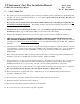
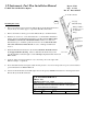
Mounting Procedure:
1. Find a convenient location within 8" of a hose support or fitting and away from any hot exhaust pipes to suspend the Fuel Flow
Transducer. The hose support or fitting may be on the input or output line of the Flow Transducer.
2. Remove the fuel hose which goes from the Carburetor to the Fuel Tank.
3. Purchase two new hoses, one from the Carburetor to the Fuel Flow Transducer and the other from the Fuel Flow Transducer to the
Fuel Tank. There must be flexible hose in and out of the Transducer. The hoses must meet TSO-C53a Type C or D FAA
specification. The new hoses must be the same diameter as the current hose in the aircraft.
4. Mount the Fuel Flow Transducer in the fuel supply line and in the return line for pressure carburetors. The Flow Transducer
must be wrapped with Fire Sleeving. Place a small hole in the fire sleeve and pass the transducer wires through it. Seal with
High temperature Silicone RTV sealant.
5. Before connecting fuel hose to the carburetor , verify that the boost pump delivers at least 125% of takeoff fuel consumption at
minimum fuel pressure as marked on fuel pressure gage.
J.P.INSTRUMENTS
PO Box 7033
Huntington Beach CA 92646
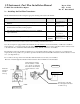
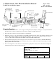
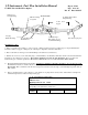
Title : Installation of a Fuel Flow Transducer in the fuel
supply or return line from the carburetor to the fuel tank
Drawing No. 700923
Date
02/14/97
Drawn/
Approved
Rev NC
8 inches
Maximum from
support
To the Fuel Tank
Fuel line from
the Carburetor
To the Fuel Tank
OUT
Fuel IN
TRANSDUCER
Aeroquip Fire
Sleeve
AE102/62-24
Fittings ¼ NPT to Fuel
Hose (do not use
aluminum fittings
Aeroquip
900591B
Clamp
Mount to
Firewall or
Engine
MS 21919 Clamp
as required
Aeroquip Fire sleeve
AE102/62-24