
Installation Manual
FAA APPROVED INSTALLATION MANUAL FOR THE EGT-701 Report 103
INSTALLING THE EGT-701 SCANNER® 1/20/09 Rev-E Page 11 of 30
13) ROUTING THE WIRING HARNESS
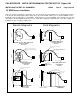
Route the wires from the probes and sensors through the firewall using fireproof rubber grommets and flame retarding
silicone. Use an existing hole if possible. Following the existing wiring harness and connect to the indicator marking
each lead with the cylinder number. All wires must be routed away from high temperature areas (exhaust stacks,
turbochargers, etc.). Secure Probe leads to a convenient location on the engine approximately 8 to 12 inches from the
probe, being sure there is sufficient slack to absorb engine torque. It is essential in routing the probe wire that this
wire not be allowed to touch metal parts of the airframe or engine since abrasion will destroy this high temperature
wire.
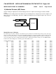
Connect the JPI RPM sensor to the wiring harness using the 3-pin connector supplied.
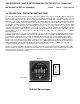
Secure thermocouple wires along the route to the indicator. Secure wire using original clamps, tie wrap if possible.
CAUTION: Be sure the wiring does not obstruct the controls under the panel.
The probe wires must not be tied in with ignition, alternator or twin engine cabin heater ignition wires because of
potential interference with temperature readings.
Temperature probe wiring harness is made of Chromel-Alumel alloy wire (yellow) that must not be substituted or
extended with normal copper wire. The power and ground wire are normal copper. Leads may be spliced with
additional Chromel-Alumel wire using copper butt splices.
When the installation is complete all wires should be secured using ties and carefully checked for interference,
rubbing or chaffing with flight control cables or other moving parts.