
Installation Manual

FAA APPROVED INSTALLATION MANUAL FOR THE EGT-701 Report 103
INSTALLING THE EGT-701 SCANNER® 1/20/09 Rev-E Page 16 of 30
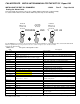
17)Installation Record
The indicator and probes FAA TSO approved, as a temperature indicator under TSO-C43b. Record the
installation of the EGT-701 per STC# SA 2586NM. Make an appropriate entry in the aircraft log book. FAA form 337
may be required.
18)Operation
Airplane flight manual limitations based on primary instrument indication take precedence over those of the EGT-701.
CAUTION: Comply with manufacturer’s airplane/rotorcraft flight manual leaning procedure. Do not exceed
applicable engine or aircraft limitations.
CAUTION
Comply with manufacturer’s Airplane/Rotor craft
Flight Manual leaning procedure.
Do not exceed applicable engine
or aircraft limitations.
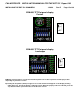
After establishing desired cruise power depress the LF button to activate the Lean Find Mode. As the mixture is
leaned, the column display on the EGT-701 for one cylinder will begin blinking; indicating the exhaust gas temperature
for that cylinder has peaked. Continue with the leaning procedure as recommended by the aircraft manufacturer while
monitoring the primary engine instruments and the EGT-701 display. Once the leaning procedure has been
completed, depress the Step button briefly to exit the Lean Find Mode and enter the Monitor Mode.
ENGINE OPERATION: Operate and lean the engine in accordance with the manufacturers’ recommendations
for different power settings. Lycoming recommends running peak EGT only at 75% power or less. Continental recommends
running peak EGT at 65% power or less.
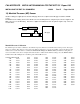
19) EGT-701 SPECIFICATIONS and LIMITATIONS
OUTPUT FUNCTIONS (ALL OPTIONS): FACTORY LIMITS
EGT (Exhaust Gas Temp.,K ,Max. limit 2500
o
F) 1650
o
F
CHT (Cylinder Head Temp., J/K Max. limit 600
o
F) 450
o
F
TIT (Turbine Inlet Temperature, K, Max. limit 2500
o
F) 1650
o
F
OIL (Oil temperature, K, Max. limit 600
o
F) (Hi/Lo) 230/90
o
F
OAT (Outside Air Temp., K, Limit -40 to 300
o
F)
IAT (Induction Air Temp., K, Max. Limit 600
o
F.)
CLD (Rate of change of CHT) -60
o
/minute
DIF (Maximum EGT differential) 500
o
F
LFM (Lean Find Mode, detects first EGT peak)
BAT (Voltage, 0 to 40 volts.) Not FAA Approved under TSO-C43b 15.5/11.0 or 31.0/22.0 Hi/Lo
RPM Tested under TSO-C43b (Does not comply with TSO-C49a)
MAP Tested under TSO-C43b ( Does not comply with TSO-C45)
The conditions and test required for TSO approval of this article are minimum performance standards. It is the
responsibility of those desiring to install this article either on or within a specific type or class of aircraft to determine
that the aircraft installation conditions are within the TSO standards.
An alarm causes the digital function to flash when the particular limit is exceeded. Factory set alarm limits for CHT
(450
o
F) and OIL (230
o
F) are lower than the actual aircraft limits. The values may be adjusted to suit individual
preference by pressing the reset button. Other factory set alarm limits are: “BAT” Voltage 15.5/11.0 or 31.0/22.0 Hi/Lo
as appropriate; “DIF” (differential Hi/Lo EGT) 500
o
F; “TIT” 1650
o
F Hi; “OIL” Lo 90
o
F; “CLD” (Rate of change of
cylinder head temperature in degrees per minute) -60 degrees/minute. The pilot should be aware of the setting of each
alarm for his particular aircraft. An alarm is “Canceled” by holding the step button in for 5 seconds and seeing
the word “OFF”. Then, only that particular alarm is canceled. Canceled alarms will not appear again until the power