
Installation Manual

FAA APPROVED INSTALLATION MANUAL FOR THE EGT-701 Report 103
INSTALLING THE EGT-701 SCANNER® 1/20/09 Rev-E Page 4 of 30
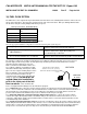
Press & hold 'STEP' and 'LF' keys simultaneously until you see
'PROGRAM' and 'RATE 4'. (Note: Bargraph disappears)
Now press & hold 'STEP' and 'LF' simultaneously again until you see
'ORIG. TIT' and 'ORIG. T-N'.
Tap 'LF' once to change to
'ORIG. T-Y'.
Tap 'STEP' once to display
'CAL TIT' and 'TIT+ 0'.
This is the correction added to (+), or subtracted from (-) the EDM reading for TIT (at high temperatures).
Hold in 'LF' to raise the correction, or tap 'LF' to lower it.
For example, if the EDM read 100 less than the ship's TIT,
Then hold in 'LF' until you see
'TIT+100'.
Adjust the correction slightly if a difference between the EDM
and the ship's gage still exists.
Now tap 'STEP' once to complete setup.
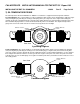
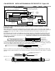
4) CYLINDER HEAD TEMPERATURE PROBE (CHT), BAYONET
The Bayonet probe 5050-T has the 3/8-24 adaptor boss as part of the probe and is screwed into the base of the
cylinder (See fig-2). The bayonet probe has a screwdriver slot to facilitate tightening.
NOTE: Required original equipment that has a Red Line may not be replaced by the EGT-701 TIT or CHT installation.
This includes but is not limited to all aircraft with adjustable cowl flaps and on aircraft with placards on the instrument
panel showing a climb air speed, for cooling, different from the best rate of climb air speed.
If a previously installed TIT, CHT or EGT is listed on the aircraft equipment list as Optional Equipment or not listed at
all, it may be replaced by the EGT/CHT SCANNER.
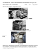
5) CYLINDER HEAD TEMPERATURE PROBE (CHT) SPARK PLUG GASKET
Most factory installed cylinder head temperature gauges utilize a bayonet or screw-in resistive type probe that
occupies one of the bayonet sockets. This probe is not compatible with the thermocouple probes required for the
EGT-701.
The spark plug gasket probe, P/N M-113, replaces the standard copper spark plug gasket on one spark plug. The
plug chosen, upper or lower, should be the one that provides the best correlation with the other temperature probes.
Due to the spark plug location, the gasket probe may read 25
o
F higher or lower than the factory probe. The probe is
usually placed on the plug that receives the most direct cooling air. After many removals the probe may be annealed
for re-use. Heat and quench in water. At additional cost an adapter probe P/N M-113-3/8 is available that permits the
factory CHT probe and a JPI probe to fit the same bayonet location.
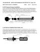
6) INDUCTION AIR TEMPERATURE PROBE (IAT) / CARB TEMP.
Induction Air temperature probe, IAT, is installed just after the inter-cooler (OUT) and the Compressor Discharge
Temp (CDT) just before the inter-cooler (IN). The probe is an EGT probe and installed the same way as an EGT
probe. A large clamp is supplied to fit around the airport leaving the inter-cooler or a 1/8 NPT is available. IAT option
is displayed as an independent digital temperature like "125 IAT". On non-turbo engines the IAT in reality is the
Carburetor temperature and displayed as “34 CRB”.