
Installation Manual

FAA APPROVED INSTALLATION MANUAL FOR THE EGT-701 Report 103
INSTALLING THE EGT-701 SCANNER® 1/20/09 Rev-E Page 8 of 30
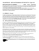
10) FUEL FLOW OPTION
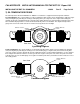
The EGT-701 receives signal from any installed Flowscan Transducer of the following Flowscan P/N’s embossed on to
the top of the transducer. The K-Factor is engraved on the side of the Transducer. Wire per drawing 700744, Route
the JPI wires along the existing wiring bundle lacing every foot.
Flowscan Instruments, Seattle WA 98106
FlowScan PN Shadin equivalent
PN
201-A
201-B 680501/680600
201-C
231 680503
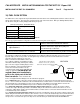
Install the function switch in the panel per drawing 700124.
Select the appropriate installation configuration from the three following fuel system categories:
For gravity feed systems without a fuel pump
use transducer FXT-231 (yellow plastic top). Connect the
transducer between the fuel tank and carburetor.
For pump feed or fuel injected systems without
vapor return lines
use transducer FXT-201 (black plastic top). Connect the
transducer between the engine driven pump and
servo/throttle body or carburetor.
For all fuel injected engines with vapor return
lines to the fuel tank before the servo/throttle.
use transducer FXT-201 (black plastic top). Connect the
transducer between the throttle body and the fuel flow divider.
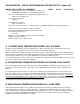
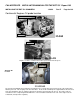
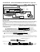
The transducer output port should be mounted lower or level with the carburetor inlet port (or fuel servo on a fuel
injected engine). If this is not possible, an anti-siphon loop should be put in the fuel line between the fuel flow
transducer and the carburetor or fuel servo.
Find a convenient location within 8 inches of a
hose support or fitting to suspend the fuel flow
transducer. Mount it away from any hot exhaust
pipes. The hose support or fitting may be on the
input or output line of the fuel flow transducer.
Secure the end of the transducer to any
convenient point on the engine with MS21919
clamps or equivalent.
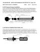
Do not place an
angled elbow joint immediately
prior to the input port of the fuel
flow transducer.
There should be two
inches of straight flow immediately before the transducer input port.
For a carbureted engine: remove the fuel hose which connects the carburetor to the fuel tank. Purchase two new
hoses — one to connect the carburetor to the fuel flow transducer, and the other to connect the fuel flow transducer to
the fuel tank. Before connecting the fuel hose to the carburetor, verify that the boost pump delivers at least 125
percent of takeoff fuel flow at minimum fuel pressure as marked on the fuel pressure gage.
For a pump-fed carbureted or fuel injected engine without vapor return lines: remove the fuel hose which
connects the engine-driven pump and the servo/throttle body or the carburetor. Purchase two new hoses one to
connect the engine-driven pump to the fuel flow transducer, and the other to connect the fuel flow transducer to the
servo/throttle body or the carburetor.
For a fuel injected engine with vapor return lines before the servo/throttle: remove the fuel hose which connects the
throttle body and the flow divider. Purchase two new hoses one to connect the throttle body to the fuel flow transducer,
and the other to connect the fuel flow transducer to the flow divider. For Continental fuel injected engines adjust the
fuel pressure to account for the pressure drop across the transducer per Continental Service Bulletin M89-10.
IN
OUT
carburetor
or servo
transducer
If the transducer is higher than the
carburetor or fuel servo, put a loop
between the transducer and carburetor
or servo
SIDE VIEW