EDM-760 Quick Reference Guide How to use LeanFind (page 13) PEAK EGT Pre-lean the mixture Tap LF button Lean the mixture Enrich to peak or 100° rich of peak Stop at peak How to Change Modes (page 7) EDM-760 enters Automatic indexing mode two minutes after power up A U T O IN D E X : p a ra m e te rs in d e x e d a u to m a tic a lly M ANUAL IN D E X : ta p S T E P b u tto n p a ra m e te rs in d e x e d w h e n S T E P is ta p p e d ta p L F b u tto n , th e n S T E P b u tto n ta p L F b u tt
Specifications FAA Approved Operating Temperature Range: Indicator TSO & STC Fuel Flow Option STC -40 to 195 oF Temperature Range: 3 1/8 in panel mount 3.5 in. sq., 7.5 in. deep EGT bar graph: variable EGT, TIT digital: -40 to 2500 oF CHT, OAT, IAT: -40 to 800 oF Common Mode Range: Analog input channels: Display Size: + 4v, rejection > 80db Analog Thermocouples Response curve: All Linearized. Resolution: 1.0 oF Accuracy: + 1.0 oF Calibration: type K (J CHT avail.
Pilot’s Guide EDM-760 TWIN Copyright 1999, 2001, 2003, 2004, 2005 J.P. Instruments, Inc. All Rights Reserved Printed in the United States of America J.P.INSTRUMENTS Information: P. O. Box 7033 Huntington Beach, CA 92646 Factory: 3185-B Airway Avenue Costa Mesa, CA 92626 (714) 557-5434 Fax (714) 557-9840 jpinstruments.com , JPITech.com and BUYJPI.
Table of Contents Section 1 - Introduction Section 2 - Displays and Controls Section 3 - Operating Procedures Section 4 - Diagnosing Engine Problems Fuel Flow Option Operation Long Term Memory Personalizing Fuel Flow Option—Formats, Diagnostics Section 5 - Option Connector Pin Assignments Reference Reading Section 6 - Technical Support Limited Warranty Index 1 4 11 23 28 34 37 48 50 51 51 52 53
Section 1 - Introduction Product Features EDM-760 Standard Instrument: • Hands-free, automatic scanning • Bar graph • • • • • • • • • • • • • LeanFind mode Battery voltage Normalize view DIF low to high EGT spread Shows largest EGT variance Oil temperature option EGTs to 1°F resolution Shock cooling monitoring Outside air temperature (OAT) option User selectable index rate Alarm “red line” limits Fast response probes Real-time serial data port Fuel Flow Option: • Solid-state pulse generating rotor fuel
With the EDM-760 it is now possible to have substantially more diagnostic information available to you in a timely and usable manner. The included data memory permits you to record all measurements for later down loading to your laptop or Palm handheld.
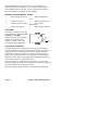
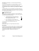
Best power range Best economy range Peak EGT 0 EGT -200 -300 20 0 CHT -20 -40 Percent power 100 -60 95 -80 Percent of best power 90 CHT °F change from best power EGT °F below peak -100 Peak Power 85 80 Spe cific fu Full Rich (Take-off) el co nsum ption Rich Lean Too lean Leaner Mixture As the mixture is leaned, EGT rises to a peak temperature, and then drops as the mixture is further leaned. Peak power occurs at a mixture using more fuel than at peak EGT.
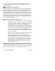
Section 2 - Displays and Controls The EDM-760 monitors engine temperatures and voltages, assists in adjusting the fuel/air mixture, and helps diagnose engine malfunctions. There are three components of the user interface: • • • Analog display including cylinder number and index dot Digital display for numeric readouts and messages Two front panel operating buttons. Displays Analog Display The upper half of the face of the EDM-760 is the analog display.
To change the display of OAT see “Pilot Programming” on page 37. To change the display of engine temperatures see “Changing the Alarm Limits” on page 44. Cylinder Numbers and Dot Index A row of numbers 1 through 6 and the letter T are the column labels for the analog display. The 1 through 6 are the cylinder numbers. If the TIT option is installed, the T denotes the last column is displaying Turbine Input Temperature (TIT).
CHT display—described later—is not affected by the Normalize or Percentage view. You may select the Normalize view in either the Manual or Automatic indexing mode. Normalize view is most helpful for engine trend monitoring of each cylinder’s operation. For example using the Normalize view during engine run-up, a fouled spark plug will appear as a higher column. A common mistake is to be in the Normalize view and then change your power setting, causing all columns to go off scale, high or low.
° F L 1 2 3 4 5 6 T C H T show n o n c a lib r a te d s c a le R P 1 2 3 4 5 6 T _ CHT 500 4 d ig it d is p la y o f EG T L e ft E n g in e % M AX 400 300 3 d ig it d is p la y of C H T L e f t E n g in e _ I4 0 I 390 STEP EG T CH T E D M -7 6 0 JPI I4 5 2 363 LF 4 d ig it d is p la y o f EG T R ig h t E n g in e 3 d ig it d is p la y of CHT R ig h t E n g in e Display Dimming The entire display panel features automatic dimming.
LeanFind Mode Simply pre-lean, tap the LF button and begin leaning. The EDM-760 will assist you in finding the first cylinder to peak. Buttons Buttons, Front Panel Two operating buttons control all functions of the EDM-760. The term tap will be used to denote pressing a button momentarily. The term hold will be used to denote pressing and holding a button for five seconds or longer. STEP Button Located on the lower left side near the instrument face.
LF Button Located on the lower right side near the instrument face. • In Automatic or Manual indexing modes, tapping the LF button will change to the LeanFind mode. • In Automatic or Manual indexing modes holding the LF button for three seconds will toggle between Percentage and Normalize views. P: Percentage view hold LF button for 3 seconds N: Normalize view • In the LF mode holding the LF button after peak EGT is found will display peak EGT.
Measurement Indexing—without Fuel Flow Option The EDM-760 steps through the engine measurements in a specific sequence. Listed below is the indexing sequence, measurement description and example of the digital display. Measurement Voltage, System Bus Outside Air Temperature Example I4.
Shock Cooling -30 -40 CLD CLD Dot indicates fastest cooling cylinder The display will pause at each measurement for four seconds in the Automatic indexing mode. (The four second indexing rate can be changed. See “Pilot Programming” on page 37.) In the Manual indexing mode, tap the STEP button to advance to next measurement. Only the measurements for the options that are installed will be displayed; uninstalled measurements will not appear.
Automatic Indexing Mode Just tap the LF button, then tap the STEP button. No user intervention is required to use this mode. In the Automatic indexing mode the EDM760 displays the measurement sequence at a user-selected indexing rate (see “Personalizing” on page 37). Individual measurements can be excluded from the Automatic indexing mode: tap STEP to enter the Manual indexing mode. Tap STEP to index to the measurement you want to exclude. Then tap both the STEP and LF buttons simultaneously.
to Change Views” in the front of this manual). You may disable the Automatic indexing mode. See “Personalizing” on page 37. LeanFind Mode—Leaning Rich of Peak • JPI’s EDM-760 provides two methods of leaning: lean rich of peak (LEAN R) or lean of peak (LEAN L). The standard method is to lean about 20° rich of peak. With the advent of GAMI injectors it is now possible to set the mixture lean of peak—saving fuel and running the engine cooler. Teledyne Continental recommends lean of peak for the Malibu.
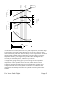
EGT °F below peak 0 Best economy range Last cylinder to peak. Use for Lean of Peak leaning with GAMI injectors -50 -100 First GAMI spread cylinder to T EG peak.
LeanFind Procedure—Step-by-Step 3 Procedure Establish cruise at approx. 65 to 75% power. Pre-lean the mixture to 50°F on the rich side of the estimated peak EGT on any cylinder: _____° Wait one minute 4 Tap the LF button 5 Slowly lean the mixture— approx. 4°/second—while observing the display. When there is a 15°F rise in EGT, LeanFind mode becomes active. 6 1 2 7 8 Example I490 370 Comments *For your first flight with the EDM-760, use the method shown below. Let engine stabilize.
LeanFind Procedure—General Explanation Lycoming and Continental engines have established specific restrictions on leaning that must be followed, such as percentage of power, climb leaning, and TIT limits. Lycoming recommends operation at peak EGT for power settings of 75% or lower, while Continental recommends operation at peak EGT for power settings of 65% or lower. This guide is not meant to supersede any specific recommendations of the engine manufacturer or airframe manufacturer.
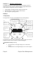
W h e n L F is a c tiv a te d : T o s h o w th e p ro g re s s o f th e le a n in g p ro c e s s , th e E D M -7 6 0 s e le c ts th e h o tte s t c y lin d e r fo r re fe re n c e in th e d ig ita l d is p la y .
the procedures defined in your aircraft engine manual. If you tap the LF button, the digital display will toggle between displaying the peak EGT or the number of degrees below peak. If you lean too much, the EGT will drop and the engine will be operating lean of peak.
the first and last to peak (GAMI Spread), as well as the richest peak EGT. L e a n in g L E A N o f P e a k L a r g e s t c o lu m n is th e fir s t c y lin d e r t o peak S h o r t e s t c o lu m n is t h e la s t c y lin d e r to peak T e m p e r a t u r e b e lo w p e a k o f t h e la s t c y lin d e r t o p e a k C u r r e n t fu e l flo w ra te ° F L 1 2 3 4 5 6 T R P 1 2 3 4 5 6 T _ CHT 500 400 % M AX 300 _ -5 7 .
limit the leaning process. TIT red line is generally 1650°F, and up to 1750°F in some installations. If during leaning the TIT exceeds red line by less than 100°, the LeanFind procedure will continue to operate and the TIT redline alarm will be suppressed for one minute, allowing you to complete the leaning process. Otherwise the digital display will show, for example, I650 TIT and TIT will flash. You will notice that in some cases the TIT reads 100°F hotter than the hottest EGT.
Take-Off, Climb, and Full Throttle Operations Suggested setup: • Percentage view • Automatic mode Verify: • EGTs and CHTs consistent with past climbs. EGTs should be in the 1100 to 1300°F range (100° to 300°F cooler than cruise) due to fuel cooling. Be alert for: • high EGT in one cylinder, 300°F above the others may indicate plugged injector or leaking manifold gasket on a carbureted engine.
Be alert for: • CLD: shock cooling alarm is set to -60°F. Average cool rates of -40°F/minute to –60°F/minute are normal, depending on the engine size. Common Misapplications Some of the more common misapplications made by first-time EDM-760 users are presented here in an attempt to help you avoid similar problems. Problem finds a premature “false” peak. Cause Failure to pre-lean before performing LeanFind. Pausing during leaning.
Section 4 - Diagnosing Engine Problems Normal Engine Limits The follow chart lists typical normal measurement values that you will observe for most general aircraft engines.
Engine Diagnosis Chart The following chart will help you diagnose engine problems in your aircraft. (Views are Percentage views). Notice that there is always one CHT that is shown hotter than the others. Display Symptom Spark plug not firing due to fouling, faulty plug, lead or distributor. Enrich mixture to return EGT to normal. Have plugs checked. Increase or decrease after ignition system maintenance Improper timing: high EGT → retarded ignition; low EGT → advanced ignition.
Display Symptom Probable Cause Recommended Action EGT and CHT not uniform Dirty fuel injectors or fouled plugs. Check injectors and plugs. Nonuniformity is normal for carbureted engines Decrease in EGT for all cylinders Decrease in airflow into the induction system. Carb or induction ice. Engine units set to Celsius Check for change in manifold pressure. Slow rise in EGT. Low CHT Burned exhaust valve. CHT is low due to low power output. Have compression checked.
Display 50% Symptom 50% 50% Recommended Action Decrease in EGT for one cylinder at low RPM Low compression. Check compression. Sudden off scale rise for any or all cylinders Pre-ignition, or Normalize view, Full rich and reduce power. Change to Percentage view. Check probe Loss of peak EGT Poor ignition or vapor in fuel injection system. Have magneto tested. Decrease in peak or flat EGT response to leaning process Detonation. Usually the result of 80 Octane fuel in 100 Octane engine.
If your installation includes a separate panel mounted alarm warning enunciator light or audible warning, it too will be activated. There is no alarm for the individual EGTs because the temperature values can assume different ranges depending on the flight configuration (run up, climb, cruise). There is an alarm on the DIF measurement, the difference between the hottest and coolest EGTs. DIF—or span—is the important measurement for monitoring the EGTs.
Pre-ignition is caused by hot spots in the cylinder. Ignition occurs prior to the spark plug firing. The EDM-760 depicts pre-ignition as a sudden red line of the EGT on the analog display. This may occur in one or more cylinders. The affected cylinder column(s) will flash while the digital display will show an EGT higher than 2000°F. At this temperature preignition will destroy your engines in less than a minute unless you take immediate corrective action.
• In the ALL (All) position, the EDM-760 both installed temperature and fuel flow measurements are displayed in the digital display in either the Automatic or Manual indexing modes or during the pilot procedure. Start Up Fuel After initial self-test, you will be asked to inform the EDM-760 of start up fuel. The EDM-760 will display FUEL for one second, and then flash FILL? N until any button is pressed.
Then tap the STEP button to complete the entry and advance to the Manual indexing mode. Adding Fuel and Auxiliary Tanks If you either a) added less than full fuel to only the main tanks, or b) topped the main tanks but have some fuel remaining in the auxiliary tanks, then select FILL + and the next display will ask you how much you added: .0 GAL (or selected units). Hold the LF button to count up, tap the LF button to count down.
inaccurate (they are only required by the FAA to read accurately when displaying empty). And measuring time of flight is only an approximation, and assumes a constant fuel flow rate for each phase of flight. The EDM-760 Fuel Flow Option uses a small turbine transducer that measures the fuel flowing into each engine. Higher fuel flow causes the transducer turbine to rotate faster which generates a faster pulse rate.
For fuel calculations to be accurate, it is imperative that you inform the EDM-760 of the correct amount of fuel aboard the aircraft. Do not rely on fuel flow instruments to determine fuel levels in tanks. Refer to original fuel flow instrumentation for primary information Measurement Indexing—with Fuel Flow Option The EDM-760 steps through the engine measurements in a specific sequence. Listed below is the indexing sequence, measurement description and example of the digital display.
F, A Total Fuel Used F, A Fuel required to next GPS WPT or Destination. Fuel Remaining at WPT F, A Nautical Miles per Gal 55 TOTL GAL USD 7.7 20.2 REQ RES 6.
Long Term Memory The EDM-760 Long Term Memory will record and store all displayed measurements once every six seconds (or at the programmed interval of between 2 and 500 seconds). At a later time, transfer them to a Palm™ handheld as an intermediate courier, or laptop PC. When you retrieve recorded data to your palmtop or laptop PC you can choose to retrieve all the data in stored in the EDM-760, or only the new data recorded since your last retrieval. In either case, no data in the EDM760 is erased.
J. P. Instruments has a downloadable data transfer application program for the Palm series called EzPalm™. Downloading the EzPalm Program from the Internet Go to our web page www.jpinstruments.com, go to the downloads page. Double click on EZPALM2.ZIP. Transferring Data from the EDM-760 to the Palm Handheld To transfer recorded data to your Palm Computer, proceed as follows: 1. Connect the Palm Computer cradle or travel cable option (available from Palm Computing) to the JPI Palm Download cable (gray).
6. On the EDM-760, tap the STEP button to begin the transfer process. The EDM-760 display shows the percentage of memory remaining to be transferred. When this number reaches zero, the transfer is complete. If you want to terminate the transfer before it is complete, simultaneously hold the STEP and LF buttons for five seconds. 7. The Palm Computer will close the file named with today’s date. Tap Exit to end EzPalm or tap Explorer to view the file list.
complete, simultaneously hold the STEP and LF buttons for five seconds. Personalizing Pilot Programming Select switch You can program the automatic indexing rate (1-9 seconds or 0 = don’t auto-index), the temperature display (°F or °C) and the EGT resolution (1 or 10°). To start the Pilot Programming Procedure, simultaneously hold the STEP and LF buttons for five seconds. You will see the word PROGRAM for two seconds and then the sequence shown in the chart below.
T, A OAT 0 OAT-I0 OAT I0 This step will be normally be skipped. See step above. Adjust the indicated temperature up or down by up to 10°. For example, OAT 3 adjust the OAT upward 3°. T, A EGT I?N EGT I? N EGT I?Y Y—Yes—sets the digital display to one degree resolution; N—No—sets 10°. (10° is easier to see.) F, A 29.00 05.00 99.99 Used to set and fine tune the K factor. See text below. KF= 05.00 Used to set and fine tune the K factor. See text below. = KF LFT F, A 29.00 99.
TIT probe must be a type K and the leads must be wired red-to-red and yellow-to-yellow. Both the EDM-760 and factory original gauge may be used concurrently. Due to the high input impedance of the EDM-760 instrument, it will not affect the accuracy of the factory installed probe or gauge. In normal cruise flight, record the difference between the factory installed TIT gauge and the EDM-760 TIT reading. TIT gauge ________ EDM ________.
• • Accumulate—default is OFF: reset the fuel used to 0 every time you inform the EDM-760 that the aircraft was refueled. With accumulate ON fuel used will not be reset to 0 when you inform the EDM-760 that the aircraft was refueled. GPS Communications fuel data format. K Factor The K factor is shown on the fuel flow transducer as a four digit number, which is the number of pulses generated per gallon of fuel flow.
Total 2. Total the EDM-760 fuel used and the actual fuel used for each tank. 3. Record the current K factor here left_________ right_________ and in the table below. 4.
2. Hold both the STEP and LF buttons simultaneously for five seconds. First digit blinks: 29.00 3. Tap or Hold the LF button to change flashing digit: 4. Tap STEP button for next digit: I9.00 I9.00 5. Tap or Hold the LF button to change flashing digit: I8.00 6. Tap STEP button for next digit: I8.00 7. Repeat items 5 and 6 for the remaining two digits. 8. Hold STEP and LF buttons simultaneously for five seconds to store the left engine K-factor. 9. KF= 29.00 is now shown. RT 10.
Tap STEP advances to next item Tap the LF button to sequence TIME MNTH DAY YEAR HOUR MIN N----- 2 500 I I2 I 3I 00 99 OO 23 OO 59 N I23456 END Y Comments Record time interval, in seconds Month Day Year (note: represents 1980 through 2079) 24 hour time. We suggest you set Zulu time This also zeros the seconds Displays current Aircraft ID. To change Aircraft ID, hold both STEP and LF buttons simultaneously until the first character flashes. Use LF to select the first character.
LO TIME 10 gal, kg, ltr, lbs 7.2 REM If you change the display to Celsius, be sure to change the alarm limits to Celsius degrees. This is not done for you automatically. When an alarm is displayed, tapping the STEP button will temporarily delete that measurement from the sequence for the next ten minutes. When an alarm is displayed, holding the STEP button until the word OFF appears will delete that measurement from the sequence for the remainder of the flight.
Changing the Alarm Limits Procedure STEP button sequences to next item LF button sequences through Description these values FAC? N FAC? Y REV X.XX ENG F ENG C EGT CHT EGT CHT I6.0 H BAT OR 30.5 H BAT ( I0.0 H BAT 35.0 H BAT ) I2.0 L BAT OR 24.0 L BAT (8.5 L BAT 30.
T IT FUEL IN FLOW GAL GALKGSLTRL BS MAIN=I00 TNK AUX? N AUX? TNK TNK AUX=0 TNK Page 46 Y Selects the units in all measurements where fuel quantity or fuel rate is displayed Main tank capacity, in units selected. Can also be set by HOLDING in the STEP Button on start up will go directly to TANK SIZE.
MIN = 45 LOW REM = I0 LOW CARB? N CARB? Y SAVE -N SAVE -Y DOT DOT SAVE -N SAVE -Y LOP LOP M IN I 0 ( 03 I ) BRT END Y END N Alarm limit in minutes for low time in tanks Alarm limit for low fuel quantity in tanks, in units selected Y—Yes—carbureted engine Whether excluded measurements are retained after power off. Y—Exclusions are saved. N—Exclusions are not saved Whether Lean of Peak method is retained after power off. Y—Lean of Peak is default.
tanks in the fuel flow units selected. If you have tank tabs and sometimes fill only to the tabs, set the auxiliary tank capacity to the difference between full tank capacity and tab capacity. The EDM-760 does not differentiate fuel flow between the main and auxiliary tanks; it tracks only total fuel in the aircraft. Low Time Alarm Limit Select the value of the time remaining, in minutes, that triggers the alarm. Time remaining is calculated at the current fuel flow rate.
Setting GPS-C Fuel Flow Communications Format GPS-C 0 1 2 3 4 5 6 Input to GPS; output of EDM-760 No fuel data output Garmin (Shadin Miniflow format) Allied Signal (format B) Arnav/EI fuel data Allied Signal (format C) * (not assigned) UPS/Garmin fuel/air data Diagnostic Messages, Fuel Flow The following displays indicate a malfunction in the Fuel Flow Option transducer or associated electrical connections: 0.0 GPH --- GPH --- H.
Navigation Data Ports for GPS Comm (These ports are completely independent of the EDM-760 serial data output port.) Navigation Data (output of GPS; input to EDM-760) Compatible with RS-232, TTL, RS-423, RS-422 SDA. Serial data format 8 data, 1 start, no parity. Baud rates: 1,200, 4,800, or 9,600 depending on the GPS data output format. The EDM-760 automatically detects the GPS data output format and is independent of the GPS-C setting.
Reference Reading You may wish to know more about the effect of engine operations on EGT and CHT. The reading list below provides general overviews as well as original references on topics that may be of interest. General Overview These references are readily available to pilots and provide a readable source of general technical information. • Teledyne Continental Motors, Engine Operation for Pilots, from the FAA Accident Prevention Program, FAA-P-874013.
Limited Warranty J.P. Instruments, Inc. (JPI), warrants all parts in your new EDM-760 to be free from defects in material and workmanship under normal use. Our obligation under this warranty is limited to repair or exchange of any defective part of this unit if the part is returned, shipping prepaid, within two years for electronics and one year for probes from the date of original purchase. Installation labor is the responsibility of the aircraft owner.
Index A Accumulate.................................38, 42 Accumulate........................................... total..............................................30 Adding fuel.......................................30 Alarm limits.......................................... factory defaults............................43 Alarms...............................................26 resetting.......................................27 ALL...................................................38 ALL........................
Flashing display..............15, 20, 26, 28 Flat EGT response............................26 Fuel....................................................... injectors.......................................19 injectors, clogged...............2, 21, 25 Octane..........................................26 pump............................................26 tank capacity..........................29, 47 Fuel flow............................................... alarm limits.................................47 units.......
temperature scanner......................4 Option connector...............................50 Outside air temperature..............10, 32 P Peak EGT..........................................16 PEAK EGT.................................15, 17 Percentage view..................................5 Personalizing.....................................37 Pilot programming............................37 alarm limits.................................43 data recording..............................42 fuel flow option........