JA SOLAR JA SOLAR PV MODULES INSTALLATION MANUAL ERT TT ot PTL Bulling No 8, Nuo District, Belling, C! Tel: Fax: +86 (10) 83611999 Etna Road, Fantail Varanasi no.
1. INTRODUCTION Thank you for choosing JA SOLAR modules! This Installation Manual contains essential: information for electrical and mechanical installation that you must know before handing and instating JA Solar Mo dives. This Anus’ 5'so contains safety information you need to be familiar with.
JA Solar Modules are designed to meet the requirements of IEC 81215 and 1EC 61730, application class A Modules rated for use In this application class may be used In system operating at greater than SOV DC or 240W, whets general contact access Is anticipated Modules qualified for safely through [EC 81730-1 and IEC 61730-2 and within this application class are considerable to meat the requirements for safety class || equipment.
Operating Safely Do not open the package of JA Solar modules until they ars ready fo be installed during transportation and storing. Al the same ime peas protect the package against exposure to damage. Secure pallets from falling aver. {io nol exceed the maximum hail of pa els io be slacked, as Indicated on the palmist packaging Store pallets in a ventilated, rain-proof and dry location until the Modes are ready to be unpacked.
| eee Solar modules ane Intended for use In terrestrial applications, no outer space use. {30 not use mirrors of other magnifiers fo concentrate sunlight ante the modules Modules must be mounted on appropriate mounting brochures positioned on suitable buildings, the ground, or other brochures suitable {for modules (e.g. carports, bulling facades or FY trackers) Modules must not be installed in locations where that could be submerged in water.
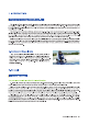
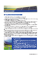
&. Mechanical Installation magi ee eg Ensure the installation method and supporting system of modules is strong sough to withstand all the load conditions. The Installer must provide this guaranties. The installation supporting system must be tested by the third parody organization with the analysis ability of Static Chimerical, coordinator Io the eal rational or international standards.
1} For framed facials’ PERV mono double-glass modulus: A. Module shooed be attached on & supporting structure rail by metal clamps It is recommended to use the camps under the following condition or approved by system Installation: Width: Clamp A no less than 80mm, Clamp B no ‘ess than Amr; Thickness: No less than 3mm Malaria’ Aluminum Alloy, 8083-T Bolt: Stainless Testes, M8 Nut: Stainless Testes, M8 ‘Washer: Stainless Steel, M8 B. Recommends boll torus tangs: 18M m to 248m ©.
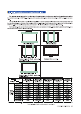
3. Installation position and corresponding static loads The anomalous level of load condition is applicable io the installation in most of environmental conditions: the maximum static load on the back of ihe modules is 2400 Pa.e. wind load), and the maximum static load on the front of modules is 2400 Pa (Le.
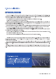
6. Electrical Installation | sell eh The rated hierarchical characteristics, isc ls within 4 % and Voc ls within measured values at Standard Test Conditions, But for the Freak, 1 1s within + 3%. Standard Test Conditions: 1000WIn? Radiance, 250 Call Temperature and 1.5 Air Mass Under normal conditions, the photovoltaic modules may experience conditions that produce more current and/or voltage than reported at Standard Lost Conditions.
2 Cables and Wiring Tess junction boxes have been designed to be easily Interconnects In series for their eel-cornecied cable and the connector with 1PE8 protection grade. Each module has two singe-conductor wires, one palliative snd one negative, which are per-wired slide the Junction box.
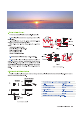
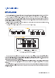
7. Grounding The grounding is only used on the framed fascia’ modules JA Solar modules use an anodize oxidized aluminum frame to resist corrosion. So the frame of modules must be connected to the prurient grounding conductor to prevent thunder and static hurl The grounding device should duly contact with the inside of the aluminum alloy, and penetrate the surface of the frame oxidation fim.
re eet The existing mounting holes which have not been used can be used for grounding A Direct the grounding clamp to the mounting hole on the frame. Thread the grounding clamp and tha frame with grounding bolt. #8. Put the toothed gasket info the other side, then tighten and lock the nut. The commendatory torque of locking the mit ls 2.0 N.m~2 2 Nm. ©. Thread the grounding camp with grounding wire.
2. Inspection of the connector and the cable It's recommended to implement the following preventive maintenance every § months: A. Check the encapsulation of the connector with the cable. Hack the sealing gel of the Junction box to ensure If Is not cracked or craved PRODUCT SUPPLEMENT The installation manual applicable mod's types are as follows.