
Operation Manual

AC-8014/814 receiver 1 / 2 MJQ51505
The AC-8014/814 receiver
The AC-8014 is a 14-channel receiver of signals from TP-8x wireless
thermostats working on a frequency of 868 MHz. It can also be used
with TP-8x digital bus thermostats. The AC-8014 can efficiently control
multi-zone heating (including thermoelectric actuating valve-drivers to
replace thermostats on radiators) or cooling systems. The receiver has
a special MODE channel which turns the heating to economy mode. It is
designed for heating system control and is not suitable for extending
hardwired alarm systems via wireless detectors.
Due to the maximum current limits of the outputs, pulses switching the
outputs off for short moments are used (when more then 8 outputs are
used). Therefore the AC-8014 should only be used with thermoelectric
actuating valve-drivers. It should not be used to control any relays,
semiconductor switches etc. LEDs on the receiver’s front cover indicate
the status of each output channel.
The AC-8014 can be considered a hybrid of two components: the
AC-814 digital bus receiver and the wireless module. The AC-814 only
allows connection by digital bus and can be supplied standalone as a
cut-down variant of the AC-8014.
The AC-8000R built-in power relay module can be used as a pump
control. A second AC-8000R module can be plugged-in to provide boiler
control. Both relays work with OR logic: they are switched if any of the
1–14 outputs is activated.
Installation
Attach the unit to the desired location with three screws. Route all the
cables to the unit before you tighten the case.
Fix the cables firmly inside the box by a sliding strap.
Note: Only a qualified technician should provide installation and
servicing. The user is not allowed to open the cover and/or make
any modifications. The mains cable must also be fixed outside the
receiver’s case. Replace the mains plug if necessary for your
country.
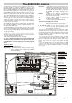
Terminal description:
AC, AC – power input 24 V AC.
SUM (summer) – input terminal. When switched to ground, economy
mode is activated. This is indicated by the MODE
channel LED lighting.
FRE (freeze) – output terminal. If any of the thermostats sends a
signal about the temperature being under the value
of the ALLo (critically low temperature) parameter in
the thermostat, this terminal switches to ground for
10 seconds. The terminal’s maximum load is
100mA.
BUS,BUS – terminals for the digital bus connection (for
thermostats of the relevant type). Maximum length
of the connection cable is 200m.
1–14 – channel outputs, switchable to ground. The
AC-8014 has pulsed switching.
COM – common positive output terminals 24V DC.
Terminals of the AC-8000R power module:
L_A, N_A, PE_A – power supply input for the circulatory pump or
boiler (use an external fuse for its protection).
L_B, N_B, PE_B – terminals for the circulatory pump or boiler
connection (the L_B terminal is triggered if any of
the 1–14 outputs are switched on).
The receiver is protected against shorts on the output. If the output is
overloaded (the current is greater than 0.4A), then the output is
automatically disconnected. A fault is indicated by rapid red flashing
of the corresponding LED indicator. The output is under constant
monitoring and when the output current decreases below 0.4A the
output will be switched on again.
If it is necessary to have more channels, then it is possible to
connect another unit via a 4-wire cable connected to terminals 1–4. In
this case a single wireless unit should be shared by both receivers.
However, each receiver only controls its own built-in AC-8000R
module.
There is an available connector for an external antenna (e.g. AN-80
or AN-81) on the bottom side of the front housing. If the external
antenna is used no further modifications to settings or connections
are necessary.
Fuse T 400 mA
P
B
L_B
N_B
PE_B
L_A
N_A
PE_A
Second module
connection
8000R
Built-in 8000R module
Antenna connection
SUM
FRE
GND
1
2
3
4
Terminals for
auxiliary signals
Wireless module
Terminals for
digital bus thermostats
Terminals for multiple
AC-8014 wiring
Connecting cable
Pump module connection
Boiler module connection
Terminals 24 V AC
Fuse box
Fuse 3.15A
Channels 1-14
output terminals
Power supply