
User's Manual
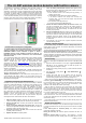

JA-84P wireless motion detector with built-in camera JA-84P_en_PTS1
The photo is then stored in memory. For the next 5 seconds from the
moment of taking the photo shot, the detector goes to sleep mode. After
that the detector returns to watching out for movement. Any further
detection of movement is reported and responded to according to whether
the system is in an entrance delay state and/or alarm condition. If an
entrance delay is still occurring, the detector will not take or store pictures
any more. If an alarm state is indicated, the detector will take photos the
same way as if a movement had been detected in an instant loop (see
below). If an alarm triggered due to an entrance delay has expired (so
that no other detectors have been triggered), then the memorized photo
taken during first movement detection is transmitted.
Instant-loop movement detection is reported to the control panel and
captured by a series of 4 photos taken by the camera. The first photo is
taken instantly without a flash. The following 3 pictures are taken at one
second intervals, each with a flash. After that any movement in the
detection area is ignored and the pictures are transferred to the control
panel. The detector’s inactivity period ends 5 seconds after finishing
picture transmission.
Alarm verification and flash functions
The main task of the built-in camera is to verify real alarms caused by
human body movement (to recognize false alarms).
The detector’s built in flash illuminates the scene, but it also has another
important functions patented by Jablotron:
a) An unexpected flash attracts the intruder to look at the detector
and this significantly increases the probability that the next shot will
show the intruder’s face
b) A flash also clearly indicates, to the intruder that he was detected,
possibly making him run away. If not and (s)he tries to damage the
detector, a tamper alarm is triggered. The tamper alarm will verify the
intruder’s presence even faster than photo transmission does.
Viewing photos from the detector’s internal memory
The detector stores the last 61 photos in its internal memory. The
photos can be viewed by a PC:
1. Switch the control panel to SERVICE mode
2. Open the detector and disconnect the camera module’s cable
3. Take the cover with the camera to the PC and use the cable
(provided with the JA-80Q data module) to connect it to the PC USB
port
4. The camera module is accessible as a removable mass storage
device. Photos are stored in BMP files. Use a suitable viewer (i.e.
“Windows photo and fax viewer”) to view the photos.
5. After viewing the photos reinstall the camera module in the detector
and switch the control panel to normal operational mode.
Detector DIP switches
There are 4 DIP switches to select the desired features:
1
OFF = delay reaction (exit & entrance delay provided)
ON = instant reaction (no exit & entrance delay)
This switch only has an effect if the detector’s address has a NATUR
reaction programmed in the control panel
2
OFF = standard immunity for the motion sensor
ON = increased immunity for the motion sensor (slower reaction)
3
OFF = flash disabled (except for testing)
ON = flash enabled (second to fourth shots with flash)
4
OFF = photos stored only in the camera (not transmitted)
ON = photos stored in the camera memory and also transmitted
wirelessly to the control panel
Bold = factory default setting
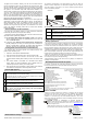
Motion detector coverage
The detection characteristics of the PIR detector lens does not affect the
detector‘s camera components. The default lens supplied covers an angle of
120° and a distance of 12 metres. The area is covered by three beams as
shown in the following diagram.
Side view
Top view
The characteristics can be changed by using optional lenses:
JS-7904
Suitable for long corridors. The middle beam covers 20
meters.
JS-7906
Only employs an upper beam with a 120° angle and a 12
metre range. Ignoring the floor helps eliminate the effect of the
movement of small pets.
JS-7901
Has a vertical beam forming a wall-like detection barrier which
triggers the detector if someone walks through it.
Note: After changing the lens, test that the desired area is protected. Incorrect
installation of the lens can disable detection.
Battery replacement
The detector monitors the voltage of its batteries and if too low, a transmission
is sent to the control panel to inform the installer or user. The detector continues
to function and shows each detected movement with a flash of its red LED.
Battery replacement should not be delayed by more than a couple of days. This
should be done by a qualified technician with the control panel in Service mode.
After battery replacement, the detector needs about 100 sec to stabilise during
which its red LED lights continuously. After the LED has stopped indicating, test
that the detector is functioning (it will be in test mode for 15 minutes).
Always use new batteries and replace both of them. Be careful not to mix
used and new batteries (even a nearly discharged lithium battery has 3V so it
is not simple to recognize a discharged battery).
Expired batteries should not be thrown into the garbage, but disposed of
according to local regulations.
Removing the detector from the system
If a detector is removed, the control panel reports its removal. The detector
has to be deleted from the control panel before intentional removal.
Technical parameters
Voltage: 2x Lithium battery type CR14505 (AA 3.0V)
Typical battery lifetime: approx. 3 years (max. 80 photo sequences)
Communication band: 868 MHz, Oasis protocol
Communication range: max. 300m (open area)
Recommended installation height: 2.0 to 2.5 m above floor level
PIR detection angle/detection range: 120° / 12 m (with basic lens)
Resolution of the camera 160 x 120 pixels, B&W
Internal memory photo format bit map (BMP)
Format of the photos transmitted to server JPG
Horizontal camera capture angle 50°
Range of the flash max. 3 meters
Typical photo transmission time to the control panel 12 sec
Typical photo transfer time from the system to server 8s/GPRS (JA-80Y)
2s /LAN (JA-80V)
Operational environment according to EN 50131-1 II. internal space
Operational temperature range -10 to +40 °C
Dimensions 110 x 60 x 55 mm
EN 50131-1,CLC/TS 50131-2-2, EN 50131-5-3 classification: grade 2
Complies with ETSI EN 300220, ETS 300683, EN 60950
FCC ID: VL6JA84P
Jablotron Ltd. hereby declares that the JA-84P is in compliance with the essential
requirements and other relevant provisions of Directive 1999/5/EC. and complies
with part 15 of the FCC rules. Operation is subject to the following two
conditions: 1. This device may not cause harmful interference, and 2. This
device must accept any interference received, including interference that may
cause undesired operation.
CAUTION: Changes or modifications no expressly approved by
Jablotron could void the user´s authority to operate the equipment. The
original of the conformity assessment can be found at www.jablotron.com,
Technical Support section
Note: Although this product does not contain any harmful materials we suggest
you return the product to the dealer or directly to the producer after use.
www.jablotron.com
Tel.: +420 483 559 999
fax: +420 483 559
993
Pod Skalkou 33
466 01 Jablonec n.N.
Czech Republic