MODEL 66300B 3 TON LOW PROFILE FLOOR JACK USER'S MANUAL *This hydraulic jack conforms to all "ANSI / ASME" safety standards. Jackco Transnational Inc. © 2010 South El Monte, CA 888-452-2526 To see more jackco products please visit our website at www.jackco.
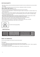
FOR YOUR SAFETY • Read these safety instructions carefully and keep this manual in an easy to find place as you may need to use it again. • Non-compliance with these rules may result in injury or damage to the jack or the vehicle. • Do not modify the jack in any way. • Never exceed the rated capacity of the jack. • This jack is a lifting device only and should never be used to move the vehicle. • The jack should be supported on a solid and level ground.
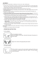
ASSEMBLY Please refer to the exploded view drawing in this manual in order to identify parts: 1. Assemble the two handle halves together by depressing the spring-loaded button on the knurled handle section (#7) and inserting the upper handle section into the lower section (#8). The spring-loaded button should engage with the hole in the lower handle section. 2. Grease the inside of the handle yoke (#11) and remove the handle set screw (#10). 3.
MAINTENANCE Important: Both the maintenance and repair of the jack may only be performed by qualified persons, who have sufficient knowledge of the hydraulic system used in these jacks Regularly lubricate the moving parts in the wheels, arms, handle and pump roller pin. • Only original replacement parts should be used. Extremely Important: never use brake fluid. • When the jack is not in use, make sure the lifting arm is fully retracted to avoid corrosion.
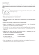
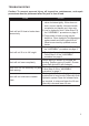
TROUBLESHOOTING Caution: To prevent personal injury, all inspection, maintenance, and repair procedures must be performed when the jack is free of load. Trouble Jack will not lift load or leaks down excessively Solution 1. The release valve is not closed. Turn the valve clockwise tightly. If this does not work, remove handle, lubricate handle receptacle and handle end, then retry. 2.Low on hydraulic fluid. Follow Step 5 of the "ASSEMBLY" procedure on page 3. 3.Pump seals or back-up ring may be defective.
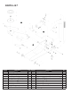
PARTS LIST Part No. 1 2 3 4 5 6 7 8 9 10 Description Retaining Ring Washer Front Wheel Rear Caster Ass'y. Hex Nut & Lock Washer Yoke Retaining Bolt & Washer Handle Lever "B" Handle Lever "A " Handle Bumper Set Screw - Handle Q'ty Part No. 2 2 2 2 2 2 1 1 1 1 11 12 13 14 15 16 17 18 19 20 Description Handle Yoke Power Unit Ass'y. Universal Joint Ass'y. Block Linkage (incl. Split Pin, Ret.
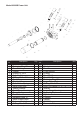
Model 66300B Power Unit Index No. 1 2 3 4 5 6 7 8 9 10 11 12 13 14 15 16 17 18 19 Description Q'ty Ram Retaining Ring 30 Ram Bearing Gasket O-Ring 31 x 4.6 Cylinder Nut O-Ring 29.6 x 3.5 Gasket Steel ball 4 Relief Valve Spring Relief Valve Bolt Sealed Washer Small Pump Housing Pump Spring Dust Cover Retaining Ring 15 Small Pump Piston Universal Joint Assembly O-Ring 10 x 2.65 1 1 1 1 1 1 1 1 1 2 2 2 1 1 1 1 1 1 2 Index No.
LIMITED ONE YEAR WARRANTY Jackco Transnational Inc. warrants all Jackco equipment and tools to the original purchaser against any manufacturing defect in material or workmanship for a period of one (1) year from the original date of purchase.