AJ-44T SERIES RACK CONVEYOR DISHMACHINE INSTALLATION/OPERATION & TECHNICAL MANUAL AJ-44T SERIES AJ-66T SERIES AJ-80T SERIES AJ-44TE AJ-44TG AJ-44TS AJ-66TE AJ-66TG AJ-66TS AJ-80TE AJ-80TS AND ASSOCIATED OPTION PACKAGES INCLUDING: SIDE LOADER September 29, 2007 P/N 7610-003-07-21 (Revision C) Jackson MSC LLC. P.O. Box 1060 Barbourville, KY. 40906 (606) 523-9795 Fax: (606) 523-9196 www.jacksonmsc.
MANUFACTURERS WARRANTY ONE YEAR LIMITED PARTS & LABOR WARRANTY ALL NEW JACKSON DISHWASHERS ARE WARRANTED TO THE ORIGINAL PURCHASER TO BE FREE FROM DEFECTS IN MATERIAL OR WORKMANSHIP, UNDER NORMAL USE AND OPERATION FOR A PERIOD OF (1) ONE YEAR FROM THE DATE OF PURCHASE, BUT IN NO EVENT TO EXCEED (18) EIGHTEEN MONTHS FROM THE DATE OF SHIPMENT FROM THE FACTORY.
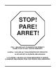
STOP! PARE! ARRET! CALL 1-888-800-5672 TO REGISTER THIS PRODUCT! FAILURE TO DO SO WILL VOID THE WARRANTY! LLAME AL 1-888-800-5672 PARA REGISTRAR ESTE PRODUCTO! AL NO HACERLO LA GARANTIA SERA ANULADA! S.V.P.
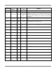
REVISION REVISION DATE A 08-03-2005 MADE APPLICABLE BY ECN DETAILS MAW 7442 Initial release of manual. Added gas exhaust fan schematic, updated electric exhaust fan schematic. Replaced rinse drain weldment 05700-021-68-28 with 05700-002-51-12. Added wash, rinse and psi decals. Changed the door assemblies. Added the rinse fill motor assembly. Added Gas Models. B 02-13-2006 MAW 7600, 7558 7462, 7367 7463 C 3-21-2006 MAW 7571 Change to new layout. Change themostats and add replacement kits.
NOMENCLATURE FOR THE MODELS COVERED IN THIS MANUAL AJ-44TS AJ = AJ series of rack conveyors 44 = 44” wide machine 66 = 66” wide machine 80 = 80” wide machine TE = Electrically heated, hot water sanitizing machine TG = Gas heated, hot water sanitizing machine TS = Steam heated, hot water sanitizing machine Jackson MSC LLC. provides technical support for all of the dishmachines detailed in this manual. We strongly recommend that you refer to this manual before making a call to our technical support staff.
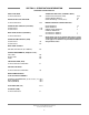
TABLE OF CONTENTS SECTION DESCRIPTION PAGE SPECIFICATION INFORMATION Operating Characteristics Electrical Requirements AJ-44T Electric - Left to Right AJ-44T Electric - Right to Left AJ-44T Gas - Left to Right AJ-44T Gas - Right to Left AJ-44T Steam - Left to Right AJ-44T Steam - Right to Left AJ-66T Electric - Left to Right AJ-66T Electric - Right to Left AJ-66T Gas - Left to Right AJ-66T Gas - Right to Left AJ-66T Steam - Left to Right AJ-66T Steam - Right to Left AJ-80T Electric - Left to Right AJ-80T
TABLE OF CONTENTS SECTION V. VI.
TABLE OF CONTENTS SECTION VII. VIII.
SECTION 1: SPECIFICATION INFORMATION 1
SECTION 1: SPECIFICATION INFORMATION OPERATING CHARACTERISTICS STEAM COIL TANK HEAT (TS MODELS ONLY): RACKS PER HOUR: AJ-44-66-80TE/TG/TS 204 STEAM INLET PRESSURE (PSIG) STEAM CONNECTION NPT CONSUMPTION @ 15 PSIG (lbs/hr): 5100 MOTOR ELECTRICAL CHARACTERISTICS: DISHES OR GLASSES PER HOUR: AJ-44-66-80TE/TG/TS PREWASH TANK CAPACITY (GALLONS): AJ-66TE/TG/TS AJ-80TE/TG/TS DRIVE MOTOR HP WASH MOTOR HP POWER RINSE MOTOR HP PREWASH MOTOR HP: AJ-66TE/TG/TS MODELS AJ-80TE/TG/TS MODELS 17.25 17.
SECTION 1: SPECIFICATION INFORMATION ELECTRICAL REQUIREMENTS NOTE: Typical Electrical Circuit is based upon (1) 125% of the full amperage load of the machine and (2) typical fixedtrip circuit breaker sizes as listed in the NEC 2002 Edition. Local codes may require more stringent protection than what is displayed here. Always verify with your electrical service contractor that your circuit protection is adequate and meets all applicable national and local codes.
4 AJ-44T Series Technical Manual 7610-003-07-21 Issued: 03-21-2006 Revised: 09-29-2007 [15mm] A Rear of Machine 1 2 6621 [1692mm] 1 [25mm] 84 [2134mm] With Doors Open Scrap Trough Minimum 14 [355mm] Left Side Drive Unit 10" High Table Backsplash 8 [203mm] 4 [102mm] 1334 [346mm] 29 [737mm] Scrap Trough 6041 [1530mm] 6221 [1590mm] 7521 [1919mm] 4" (102 mm) wide x 16" (406 mm) long cutout in Vent Cowl/Splash Shield. Shipped with Cover Plate.
AJ-44T Series Technical Manual 7610-003-07-21 Issued: 03-21-2006 Revised: 09-29-2007 5 [15mm] Rear of Machine 1 2 84 [2134mm] With Doors Open Left Side Drive Unit Note: All vertical dimensions are +/- 1/2" from floor due to adjustable bullet feet.
Rack Rail Recommended Table Fabrication Note: Tub Will Accept a Table Flange Up to 24 7/8" (632 mm) 6 AJ-44T Series Technical Manual 7610-003-07-21 Issued: 03-21-2006 Revised: 09-29-2007 [15mm] Rear of Machine 1 2 A Left Side Drive Unit 10 [254mm] 29 [737mm] Scrap Trough Drive Unit 10" High Table Backsplash 1 [1530mm] 604 2 6 [152mm] Front View C Minimum 14 [356mm] G 621 [165mm] 36 [914mm] H J K 36 [914mm] 2621 [673mm] 3141 [795mm] 6 [152mm] E D 7 [178mm] Legend to Drawing T
2 Rack Rail Recommended Table Fabrication AJ-44T Series Technical Manual 7610-003-07-21 Issued: 03-21-2006 Revised: 09-29-2007 7 [15mm] Rear of Machine 1 2 Left Side Drive Unit H G K 29 [737mm] 1 [163mm] 62 J 1 [794mm] 314 1 [672mm] 262 36 [914mm] 1 [1530mm] 604 Drive Unit Front View 10 [254mm] 7 [178mm] C 16 [407mm] B 721 [191mm] 34 [864mm] E 25 [635mm] Dish Clearance D 7 [178mm] 8 [206mm] 1821 [467mm] Right Side C 21 [533mm] 25 [635mm] Floor Sink Or Drain With 3" (76 mm)
8 AJ-44T Series Technical Manual 7610-003-07-21 Issued: 03-21-2006 Revised: 09-29-2007 [15mm] Rear of Machine 1 2 6658 [1692mm] 1 [25mm] 84 [2134mm] With Doors Open Drive Unit Left Side A Note: All vertical dimensions are +/- 1/2" from floor due to adjustable bullet feet.
9 AJ-44T Series Technical Manual 7610-003-07-21 Issued: 03-21-2006 Revised: 09-29-2007 [15mm] Rear of Machine 1 2 6658 [1692mm] 1 [25mm] 84 [2134mm] With Doors Open Drive Unit Left Side A Rack Rail 578 [148mm] 438 [110mm] 858 [218mm] J H 43 [1092mm] 1158 [295mm] 1534 [400mm] 1638 [417mm] M 6041 [1530mm] 6221 [1590mm] 2334 [604mm] L 1721 L [445mm] F 4 [102mm] K F 29 [737mm] 10 [254mm] 38 [966mm] 1141 [285mm] H 1358 [345mm] J 638 [162mm] M 641 [159mm] Tub Drive Unit B 7 [
10 AJ-44T Series Technical Manual 7610-003-07-21 Issued: 03-21-2006 Revised: 09-29-2007 [15mm] Rear of Machine 1 2 6621 [1692mm] 1 [25mm] 3 [79mm] 84 [2134mm] With Doors Open Drive Unit G Left Side 6 [152mm] A F Note: All vertical dimensions are +/- 1/2" from floor due to adjustable bullet feet.
11 AJ-44T Series Technical Manual 7610-003-07-21 Issued: 03-21-2006 Revised: 09-29-2007 [15mm] Rear of Machine 1 2 6621 [1692mm] 1 [25mm] 3 [79mm] 84 [2134mm] With Doors Open Drive Unit G Left Side 6 [152mm] A F Rack Rail 6221 29 [737mm] Drive Unit 6041 [1530mm] [1590mm] 8 [203mm] 4 [102mm] 7521 [1919mm] B A F 4 1/2 [114mm] Tub Front View 6 [152mm] 10 [254mm] 24 [610mm] A 42 [1067mm] 41 [1041mm] C 2321 G [599mm] 24 [610mm] B 34 [864mm] E 25 [635mm] Dish Clearance D 7 [1
12 AJ-44T Series Technical Manual 7610-003-07-21 Issued: 03-21-2006 Revised: 09-29-2007 [15mm] Rear of Machine 1 2 84 [2134mm] With Doors Open 3 [79mm] Drive Unit Left Side 6 [152mm] [105mm] L M A 441 7521 Rack Rail 29 [737mm] Scrap Trough Drive Unit 10" High Table Backsplash 6041 [1530mm] 4 [102mm] 221 [61mm] 41 [1040mm] 2321 [598mm] 24 [609mm] L 1441 [363mm] 6 [154mm] 141 [35mm] 3/4" (19 mm) Table Turndown Flange 3/4" Max Note: Tub Will Accept a Table Flange Up to 24 7/8" (632 mm)
13 AJ-44T Series Technical Manual 7610-003-07-21 Issued: 03-21-2006 Revised: 09-29-2007 [15mm] Rear of Machine 1 2 Left Side 6 [152mm] Drive Unit [1530mm] 6041 H G 29 [737mm] 621 [163mm] J K 36 [914mm] [794mm] 2621 [672mm] 3141 [1590mm] 6221 Drive Unit 24 [610mm] Front View 6 [152mm] 10 [254mm] 16 [407mm] M 1041 [260mm] C 34 [864mm] E 25 [635mm] Dish Clearance D 7 [178mm] 12 [307mm] 821 [217mm] 6641 [1684mm] Right Side C Legend Recommended Table Fabrication Note: Tub Will
14 AJ-44T Series Technical Manual 7610-003-07-21 Issued: 03-21-2006 Revised: 09-29-2007 [15mm] Rear of Machine 1 2 6621 [1692mm] 3 [79mm] 1 [25mm] 84 [2134mm] With Doors Open Drive Unit N O Left Side 6 [152mm] A 6014 Tub 41 [1040mm] 2321 [598mm] 24 [609mm] 29 [737mm] Scrap Trough Drive Unit 10" High Table Backsplash [1530mm] Table A Front View 6 [152mm] 1721 [445mm] [316mm] B E D F 7 [178mm] 8 [206mm] 18 [457mm] 74 [1883mm] 82 [2086mm] Overall 1221 27 [687mm] 24 [610mm] C
15 AJ-44T Series Technical Manual 7610-003-07-21 Issued: 03-21-2006 Revised: 09-29-2007 [15mm] Rear of Machine 1 2 6621 [1692mm] 1 [25mm] 3 [79mm] 84 [2134mm] With Doors Open G Left Side 6 [152mm] Drive Unit A F Note: All vertical dimensions are +/- 1/2" from floor due to adjustable bullet feet.
16 AJ-44T Series Technical Manual 7610-003-07-21 Issued: 03-21-2006 Revised: 09-29-2007 [15mm] Rear of Machine 1 2 [1692mm] 1 [25mm] 3 [79mm] 6621 84 [2134mm] With Doors Open Drive Unit G Left Side 6 [152mm] A F Note: All vertical dimensions are +/- 1/2" from floor due to adjustable bullet feet.
17 AJ-44T Series Technical Manual 7610-003-07-21 Issued: 03-21-2006 Revised: 09-29-2007 [15mm] Rear of Machine 1 2 6621 [1692mm] 1 [25mm] 3 [79mm] 84 [2134mm] With Doors Open Drive Unit G Left Side 6 [152mm] A F Rack Rail 4 [102mm] 7 [178mm] [1921mm] 29 [734mm] Drive Unit Front View 10 [254mm] A 41 [1042mm] 42 [1069mm] 96 [2441mm] Overall 6041 [1529mm] 6221 [1590mm] 7521 F 4 1/2 [114mm] C B 6 [152mm] B 34 [864mm] 25 [635mm] 12 [307mm] 821 [217mm] 6614 [1684mm] Right Side
18 AJ-44T Series Technical Manual 7610-003-07-21 Issued: 03-21-2006 Revised: 09-29-2007 [15mm] Rear of Machine 1 2 6621 [1692mm] 1 [25mm] 3 [79mm] 84 [2134mm] With Doors Open Left Side 6 [152mm] Drive Unit M A L Note: All vertical dimensions are +/- 1/2" from floor due to adjustable bullet feet.
Recommended Table Fabrication 19 AJ-44T Series Technical Manual 7610-003-07-21 Issued: 03-21-2006 Revised: 09-29-2007 [15mm] Rear of Machine 1 2 6621 [1692mm] 1 [25mm] 3 [79mm] 84 [2134mm] With Doors Open Drive Unit M Left Side 6 [152mm] A L Note: All vertical dimensions are +/- 1/2" from floor due to adjustable bullet feet.
AJ-44T Series Technical Manual 7610-003-07-21 Issued: 03-21-2006 Revised: 09-29-2007 20 [15mm] Rear of Machine 1 2 6621 [1692mm] 1 [25mm] 3 [79mm] 84 [2134mm] With Doors Open Left Side 6 [152mm] Drive Unit O A N Note: All vertical dimensions are +/- 1/2" from floor due to adjustable bullet feet.
21 AJ-44T Series Technical Manual 7610-003-07-21 Issued: 03-21-2006 Revised: 09-29-2007 [15mm] Rear of Machine 1 2 6621 [1692mm] 1 [25mm] 3 [79mm] 84 [2134mm] With Doors Open Drive Unit G Left Side 6 [152mm] A F Note: All vertical dimensions are +/- 1/2" from floor due to adjustable bullet feet.
SECTION 1: SPECIFICATION INFORMATION SIDE LOADER (LEFT TO RIGHT) DIMENSIONS 1/2” MINIMUM NOTE: ALL DIMENSIONS ARE TYPICAL. DISHTABLE USE SILICONE BETWEEN TABLE AND LIP OF SIDE LOADER TO PREVENT LEAKAGE. WALL OF SIDE LOADER 4 1/2” MINIMUM 1/2” 25” DISHWASHER 5” SECTION “A-A” 12 1/2” A 1” 8” or 15” depending on the width of the side loader. A 20 3/4” OPENING SPLASH SHIELD 1 1/2” TABLE ROLL VENT CONNECTION OPENING CONVEYOR DISHMACHINE 23” or 30” depending on the width of the side loader.
SECTION 1: SPECIFICATION INFORMATION SIDE LOADER (RIGHT TO LEFT) DIMENSIONS DISHTABLE 1/2” MINIMUM USE SILICONE BETWEEN TABLE AND LIP OF SIDE LOADER TO PREVENT LEAKAGE NOTE: ALL DIMENSIONS ARE TYPICAL. WALL OF SIDE LOADER 1/2” 25” DISHWASHER 5” SECTION “A-A” 4 1/2” MINIMUM 12 1/2” CENTER LINE DISHMACHINE VENT CONNECTION OPENING 1 1/2” TABLE ROLL SPLASH SHIELD 23” or 30” depending on the width of the side loader.
SECTION 1: SPECIFICATION INFORMATION SIDE LOADER (INSTALLED) DIMENSIONS 23” SIDE LOADER DIMENSIONS MODEL DIMENSIONS AJ-44T AJ-66T AJ-80T 75” 97” 111” (Left to Right installation shown for reference.) 30” SIDE LOADER DIMENSIONS MODEL DIMENSIONS AJ-44T AJ-66T AJ-80T 82” 104” 118” NOTE: ALL DIMENSIONS ARE TYPICAL. 10” 4” 34” 23” or 30” depending on the width of the side loader. Refer to chart above.
SECTION 2: INSTALLATION & OPERATION INSTRUCTIONS 25
SECTION 2: INSTALLATION/OPERATION INSTRUCTIONS INSTALLATION INSTRUCTIONS NOTE: THE INSTRUCTIONS PROVIDED HEREIN, UNLESS OTHERWISE SPECIFIED ARE FOR THE DISHMACHINES ONLY. THERE ARE SEPARATE DIRECTIONS FOR THE GAS BOOSTER. VISUAL INSPECTION: Before installing the unit, check the container and machine for damage. A damaged container is an indicator that there may be some damage to the machine. If there is damage to both the container and machine, do not throw away the container.
SECTION 2: INSTALLATION/OPERATION INSTRUCTIONS INSTALLATION INSTRUCTIONS (CONTINUED) STEAM LINE CONNECTIONS: Some machines covered in this manual are designed to use low pressure steam as a source of heat for wash tank water. The machines come with lines by which outside source steam needs to be connected. Connect all incoming steam lines in accordance with the steam booster manufacturer’s instructions. Ensure that all applicable codes and regulations are adhered to.
SECTION 2: INSTALLATION/OPERATION INSTRUCTIONS INSTALLATION INSTRUCTIONS (CONTINUED) ELECTRIC HEAT: The thermostats for the machines covered in this manual are factory set. They should not be adjusted except by an authorized service agent. CHEMICAL FEEDER EQUIPMENT: Detergent may be introduced into the unit through the removal of the bulkhead plug in the rear of the tub and replacing it with the third party detergent injection fitting.
21" 29 AJ-44T Series Technical Manual 7610-003-07-21 Issued: 03-21-2006 Revised: N/A 21" L S 12" L L S 12" L S 12" L 21" 66 44 21" L 80 21" L R 12" S ELECTRIC & STEAM MACHINES L 21" S R 12" S L 12" S L 12" L 21" S R 12" 12" S 21" L 21" L UNHOODED SIDE LOADER 21" L UNHOODED SIDE LOADER S R 12" L L 21" L L 21" L 21" L 21" 12" S 12" S 21" L HOODED SIDE LOADER 12" S HOODED SIDE LOADER S R 12" L 21" S R 12" SECTION 2: INSTALLATION/OPERAT
SECTION 2: INSTALLATION/OPERATION INSTRUCTIONS DELIMING OPERATIONS DELIMING OPERATIONS: In order to maintain the dishmachine at its optimum performance level, it will be required to remove lime and corrosion deposits on a frequent basis. A deliming solution should be available from your detergent supplier. Read and follow all instructions on the label of the deliming solution.
SECTION 2: INSTALLATION/OPERATION INSTRUCTIONS SIDE LOADER INSTALLATION & OPERATION INSTRUCTIONS This accessory assists in the delivery of a full dish rack from the break down (scrapping) table to the dishmachine. It will convert the direction of travel 90°. Since the Side Loader is shipped mounted on the conveyor dishwasher there is no additional installation required for this option. As it is operated mechanically by the dishwasher it does not require any plumbing or electrical connections.
SECTION 2: INSTALLATION/OPERATION INSTRUCTIONS DISHMACHINE OPERATING INSTRUCTIONS PREPARATION: Before proceeding with the start-up of the unit, verify the following: 1. Close door(s) on dishmachine. 2. Close the drain valve(s). POWER UP (ELECTRICALLY-HEATED MODELS): To energize the unit, turn on the power at the service breaker. The voltage should have been previously verified as being correct. If not, the voltage will have to be verified.
SECTION 2: INSTALLATION/OPERATION INSTRUCTIONS DISHMACHINE OPERATION INSTRUCTIONS (CONTINUED) SHUTDOWN AND CLEANING (ELECTRICALLY-HEATED MODELS): At the end of the workday, place the power switch in the OFF position and open the door(s). Open the drain valves and allow the machine to drain completely. Remove the pawl bar assembly (clean as required). Remove the pan strainers and, if equipped, the prewash strainers, run off sheets and scrap basket strainer.
SECTION 2: INSTALLATION/OPERATION INSTRUCTIONS DETERGENT CONTROL Detergent usage and water hardness are two factors that contribute greatly to how efficiently your dishmachine will operate. Using detergent in the proper amount can become, in time, a source of substantial savings. A qualified water treatment specialist can tell you what is needed for maximum efficiency from your detergent, but you should still know some basics so you’ll understand what they are talking about.
SECTION 2: INSTALLATION/OPERATION INSTRUCTIONS STRIKER PLATE LIMIT SWITCH INSTALLATION INSTRUCTIONS Installation Instructions: 1. Wiring: The switch is wired common and normally open because of the hinge design. By interrupting the line in series with the door switches, the dishmachine ceases to operate. Refer to the machine schematic for details on how to wire the switch. 1/3 RACK WIDTH INSTALL AT FAR END OF TABLE 2.
SECTION 3: PREVENTATIVE MAINTENANCE 36
SECTION 3: PREVENTATIVE MAINTENANCE PREVENTATIVE MAINTENANCE The dishmachines covered in this manual are designed to operate with a minimum of interaction with the operator. However, this does not mean that some items will not wear out in time. Jackson highly recommends that any maintenance and repairs not specifically discussed in this manual should be performed by QUALIFIED SERVICE PERSONNEL ONLY.
SECTION 3: PREVENTATIVE MAINTENANCE LUBRICATION CHART FOR DRIVE GEAR Note: The maintenance procedures detailed here are manufacturer’s instructions for the WINSMITH brand of gear reducer that is installed on the rack conveyors covered in this manual. Ambient Temperature Final Stage Worm Speed1 ISO Viscosity Grade AGMA Lubricant No.
SECTION 3: PREVENTATIVE MAINTENANCE DRIVE MOTOR GEAR REDUCER PREVENTATIVE MAINTENANCE Note: The maintenance procedures detailed here are manufacturer’s instructions for the WINSMITH brand of gear reducer that is installed on the rack conveyors covered in this manual. Lubrication & Maintenance: Factory filling - WINSMITH speed reducers are oil filled at the factory to the proper level for the standard mounting position that you will find it in on the unit.
SECTION 4: TROUBLESHOOTING SECTION 40
SECTION 4: TROUBLESHOOTING COMMON PROBLEMS WARNING: Inspection, testing and repair of electrical equipment should be performed only by qualified service personnel. Certain procedures in this section require electrical tests or measurements while power is applied to the machine. Exercise extreme caution at all times. If test points are not easily accessible, disconnect power, attach test equipment and reapply power to test.
SECTION 4: TROUBLESHOOTING COMMON PROBLEMS Problem: Pawl bar does not move. 1. Failed or broken overload spring. Replace spring if necessary. 2. No power to the drive motor/failed drive motor. Verify power and wiring connections to the motor. If necessary, replace the motor. 3. Pawl bar not properly installed. Verify that the pawl bar is installed correctly. Problem: Racks go through the machine, but results are poor. 1.