HOT WATER SANITIZING UNDERCOUNTER DISHMACHINES TECHNICAL MANUAL INSTALLATION MANUAL FOR EXPORT UNITS SERVICE MANUAL FOR DOMESTIC UNITS FOR JACKSON MODELS: JP-24 JP-24F JP-24B JP-24BF An March 6, 2006 P/N 7610-002-49-79 (Revision D) Company Jackson MSC, Inc. P.O. BOX 1060 HWY. 25E BARBOURVILLE, KY. 40906 FAX (606) 523-9196 PHONE (606) 523-9795 www.jacksonmsc.
REVISION REVISION DATE MADE BY APPLICABLE ECN A 07-15-2002 MAW 6527 B 06-04-2003 MAW 6673, 6681 6637 Updated per ecns. C 02-11-2004 MAW 6836 Updated per ecns. D 03-06-2006 MAW 7421, 7231 6964, 7095 DETAILS Release manual for service use. Change thermostat from 05930-121-71-29 to 05930-510-03-79. Change thermostat from 05930-121-71-36 to 05930-011-49-43.
NOMENCLATURE FOR THE MODELS COVERED IN THIS MANUAL JP-24B JP-24 = Undercounter, high temperature, hot water sanitizing, no booster tank. JP-24F = Undercounter, high temperature, hot water sanitizing, no booster tank, with top and side panels. JP-24B = Undercounter, high temperature, hot water sanitizing, with a booster tank. JP-24BF = Undercounter, high temperature, hot water sanitizing, with a booster tank, with top and side panels. Jackson MSC Inc.
TABLE OF CONTENTS SECTION I. DESCRIPTION PAGE SPECIFICATION INFORMATION Specifications JP-24/JP-24F Specifications JP-24B/JP-24BF Dimensions 2 3 4 INSTALLATION/OPERATION INSTRUCTIONS Installation Instructions Electrical Installation Instructions Operation Instructions Detergent Control Cycle Counter Retrofit Kit Instructions 6 7 8 9 10 PREVENTATIVE MAINTENANCE Preventative Maintenance 12 IV. TROUBLESHOOTING 14 V.
SECTION 1: SPECIFICATION INFORMATION 1
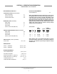
SECTION 1: SPECIFICATION INFORMATION SPECIFICATIONS of the JP-24/JP-24F ELECTRICAL REQUIREMENTS PERFORMANCE/CAPABILITIES WASH MOTOR HP OPERATING CAPACITY (RACKS/HOUR) RACKS PER HOUR 30 DISHES PER HOUR 600 GLASSES PER HOUR 600 NOTE: Typical Electrical Circuit is based upon (1) 125% of the full amperage load of the machine and (2) typical fixed-trip circuit breaker sizes as listed in the NEC 2002 Edition. Local codes may require more stringent protection than what is displayed here.
SECTION 1: SPECIFICATION INFORMATION SPECIFICATIONS of the JP-24B/JP-24BF PERFORMANCE/CAPABILITIES ELECTRICAL REQUIREMENTS OPERATING CAPACITY (RACKS/HOUR) WASH MOTOR HP RACKS PER HOUR 30 DISHES PER HOUR 600 GLASSES PER HOUR 600 NOTE: Typical Electrical Circuit is based upon (1) 125% of the full amperage load of the machine and (2) typical fixed-trip circuit breaker sizes as listed in the NEC 2002 Edition. Local codes may require more stringent protection than what is displayed here.
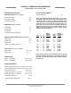
SECTION 1: SPECIFICATION INFORMATION JP-24 DIMENSIONS 2 1/2” (6.4 cm) Min. Wall Clearance LEGEND A - Water Inlet 1/2” ID Female Pipe Thread, 2 1/2” AFF B - Detergent Feeder Connection C - Electrical Connection D - Drain Connection Flexible Hose 6’ Free Length, 1” ID x 1 3/8” OD E - Rinse Additive Connection E 12” (30.5 cm) 19” (48.3 cm) 22 5/8” (57.5 cm) C 16 3/4” (42.5 cm) DOOR OPEN D 6 1/2” (16.5 cm) E A 24 1/4” (61.6 cm) 4 1/2” (11.4 cm) B C 8 1/2” (21.6 cm) 2 1/2” (6.
SECTION 2: INSTALLATION/OPERATION INSTRUCTIONS 5
SECTION 2: INSTALLATION/OPERATION INSTRUCTIONS INSTALLATION INSTRUCTIONS VISUAL INSPECTION: Before installing the unit, check the container and machine for damage. A damaged container is an indicator that there may be some damage to the machine. If there is damage to both the container and machine, do not throw away the container. The dishmachine has been inspected and packed at the factory and is expected to arrive to you in new, undamaged condition.
SECTION 2: INSTALLATION/OPERATION INSTRUCTIONS ELECTRICAL INSTALLATION INSTRUCTIONS ELECTRICAL POWER CONNECTION: Electrical and grounding connections must comply with the applicable portions of the National Electrical Code ANSI/NFPA 70 (latest edition) and/or other electrical codes. Disconnect electrical power supply and place a tag at the disconnect switch to indicate that you are working on the circuit. The dishmachine data plate is located on the front of the machine.
SECTION 2: INSTALLATION/OPERATION INSTRUCTIONS OPERATION INSTRUCTIONS PREPARATION: Before proceeding with the start-up of the unit, verify the following: 1. The strainer is in place and is clean. 2. That the wash and rinse arms are screwed securely into place and that their endcaps are tight. The wash and rinse arms should rotate freely. POWER UP: To energize the unit, turn on the power at the service breaker. The voltage should have been previously verified as being correct.
SECTION 2: INSTALLATION/OPERATION INSTRUCTIONS DETERGENT CONTROL Detergent usage and water hardness are two factors that contribute greatly to how efficiently your dishmachine will operate. Using detergent in the proper amount can become, in time, a source of substantial savings. A qualified water treatment specialist can tell you what is needed for maximum efficiency from your detergent, but you should still know some basics so you’ll understand what they are talking about.
SECTION 2: INSTALLATION/OPERATION INSTRUCTIONS CYCLE COUNTER RETROFIT KIT INSTRUCTIONS 1. Locate the template on the front of the plastic control panel in the approximate location as shown in the diagram below. 2. Use a 3/32" diameter drill bit to drill the four mounting holes through the plastic control panel. 3. Mount the template to the front of the control panel using the screws and locknuts provided. 4.
SECTION 3: PREVENTATIVE MAINTENANCE 11
SECTION 3: PREVENTATIVE MAINTENANCE PREVENTATIVE MAINTENANCE The dishmachines covered in this manual are designed to operate with a minimum of interaction with the operator. However, this does not mean that some items will not wear out in time. Jackson highly recommends that any maintenance and repairs not specifically discussed in this manual should be performed by QUALIFIED SERVICE PERSONNEL ONLY. Performing maintenance on your dishmachine may void your warranty if it is still in effect.
SECTION 4: TROUBLESHOOTING 13
SECTION 4: TROUBLESHOOTING SECTION COMMON PROBLEMS WARNING: Inspection, testing and repair of electrical equipment should be performed only by qualified service personnel. Certain procedures in this section require electrical tests or measurements while power is applied to the machine. Exercise extreme caution at all times. If test points are not easily accessible, disconnect power, attach test equipment and reapply power to test. When replacing electrical parts, disconnect power at source circuit breaker.
SECTION 4: TROUBLESHOOTING SECTION COMMON PROBLEMS WARNING: Inspection, testing and repair of electrical equipment should be performed only by qualified service personnel. Certain procedures in this section require electrical tests or measurements while power is applied to the machine. Exercise extreme caution at all times. If test points are not easily accessible, disconnect power, attach test equipment and reapply power to test. When replacing electrical parts, disconnect power at source circuit breaker.
SECTION 5: SERVICE PROCEDURES 16
SECTION 5: SERVICE PROCEDURES RINSE SOLENOID VALVE REPAIR PARTS KIT These dishmachines are equipped with electrical solenoid valves to allow for automatic fill and rinse. These valves are designed to specific tolerances and design aspects that must be met in order to function properly.
SECTION 5: SERVICE PROCEDURES RINSE SOLENOID VALVE REPAIR PARTS KIT (CONTINUED) Loosening the conduit nut Prying open the coil wire cover 4. When replacing the coil, ensure that when removing the coil wire cover that care is taken not to damage the wires inside. Using the medium flathead screwdriver, gently use it to open the cover enough to where it could be pulled off. 7. Using a pair of channel locks, gently loosen the conduit retaining ring for the conduit nut.
SECTION 5: SERVICE PROCEDURES RINSE SOLENOID VALVE REPAIR PARTS KIT (CONTINUED) Removing the valve bonnet 13. Slowly remove the valve bonnet. Note: The spring for the plunger is located directly under the bonnet and may come free if you are not careful. Remove the plunger, spring and valve bonnet and place to the side. Removing the diaphragm 17. Remove the diaphragm retainer and then the diaphragm itself.
SECTION 5: SERVICE PROCEDURES RINSE SOLENOID VALVE REPAIR PARTS KIT (CONTINUED) 21. With the mesh screen removed, look down into the valve and verify it is not clogged. Remove any foreign objects from the valve body that would obstruct flow. 22. Reassemble the valve, reversing the steps needed to take it apart. Replace defective replacement parts with new parts from ordered kits. Ensure that components are sufficiently tightened to prevent leakage.
SECTION 5: SERVICE PROCEDURES VACUUM BREAKER REPAIR PARTS KIT These dishmachines are equipped with vacuum breakers to serve as back-flow prevention devices. ASSE requirements specify what type of back-flow prevention is necessary on dishmachines. Vacuum breakers, unlike air gaps, have certain parts that have specific tolerances and design aspects that must be met in order to function properly.
SECTION 5: SERVICE PROCEDURES VACUUM BREAKER REPAIR PARTS KIT (CONTINUED) 7. If any of these conditions are present, replace the old plunger with the new one from your kit. Verify that the new plunger is also free from defects. If it is not, contact Jackson immediately. 8. The plunger should drop into the vacuum breaker and seat. Ensure it is not flipped upside down (the orange seal ring should be up towards the top of the vacuum breaker). 9. Pick up the cap and examine it.
SECTION 5: SERVICE PROCEDURES REPLACING THE PUMP MOTOR/REPLACING THE HEATER REPLACING THE PUMP MOTOR The following list of tools will be needed to complete this procedure. 5/6” nutdriver, phillips screwdriver, 7/16” socket and ratchet, and 7/16” wrench. 1. Disconnect the electrical power to the dishwasher at the main circuit breaker box when servicing. Place a tag on the circuit box indicating the circuit is being repaired. 2. Disconnect power and conduit from dishmachine terminal block. 3.
SECTION 5: SERVICE PROCEDURES REPLACING THE DRAIN VALVE REPLACING THE DRAIN VALVE The following list of tools will be needed to complete this procedure. 5/16” nutdriver, flat screwdriver, phillips screwdriver, and 7/16” socket and ratchet. 1. Disconnect the electrical power to the dishwasher at the main circuit breaker box when servicing. Place a tag on the circuit box indicating the circuit is being repaired. 2. Disconnect the power and conduit from dishmachine terminal block. 3.
SECTION 5: SERVICE PROCEDURES RINSE REGULATING THERMOSTAT REPLACEMENT Many dishmachines comes with integral booster tanks to ensure proper temperature of the final rinse. Jackson has predominantly used two manufacturers of thermostats, EGO and Stemco. These instructions are for use with kit 06401-003-13-94, which is to replace an EGO rinse regulating thermostat with a Stemco brand. Jackson offers all of the repair parts necessary for performing this task.
SECTION 5: SERVICE PROCEDURES RINSE REGULATING THERMOSTAT REPLACEMENT Location of the thermostat bracket (JP-24). Pulling the thermostat probe and fitting from the well (Tempstar). Remove the thermostat bracket mounting nuts with the 3/8” nutdriver. Removing the wires from the thermostat. 5. Attach the jumper wires to the wires that you removed from the old thermostat. Location of the imperial brass fitting (JP-24). Attaching the jumper wires. Removing the imperial brass fitting (Tempstar).
SECTION 5: SERVICE PROCEDURES RINSE REGULATING THERMOSTAT REPLACEMENT 9. Note: regardless of the unit this is being done to, the concept is to ensure that the thermostat cannot come into contact with the heater leads or interfere with the placement of any covers. Sliding imperial fitting onto new thermostat. 6. Slide the new imperial brass fitting from your kit onto the new thermostat. What the installed thermostat should look like (Tempstar). Putting the new thermostat in the well (Tempstar). 7.
SECTION 5: SERVICE PROCEDURES RINSE REGULATING THERMOSTAT REPLACEMENT need to be run on the unit while observing the final rinse temperature. The thermostat needs to cycle so that the final rinse water meets the indicated minimums on the machine data plate for every cycle. Fitting the jumper into the mounting cup. 11. Attach the ring ends of the jumpers to the cups/screws removed from the thermostat and attach them. The white jumper is to be connected to COMMON.
SECTION 6: PARTS SECTION 29
SECTION 6: PARTS SECTION GAUGE PANEL ASSEMBLY 1 2 3 4 5 6 Dielectric Cover, Electrical Panel 05700-011-40-48 7 15 8 9 10 11 12 13 14 ITEM QTY DESCRIPTION Mfg. No.
SECTION 6: PARTS SECTION ELECTRICAL PANEL ASSEMBLY (JP-24/F 208-240 VOLT) 1 2 3 4 5 6 4 7 8 9 10 11 12 13, 14, 12 4 15 16 ITEM QTY DESCRIPTION Mfg. No.
SECTION 6: PARTS SECTION ELECTRICAL PANEL ASSEMBLY (JP-24B/BF 208-240 VOLT) 1 2 3 4 5 6 4 7 8 9 10 4 11 12, 13 4 14 15 ITEM QTY DESCRIPTION Mfg. No.
SECTION 6: PARTS SECTION ELECTRICAL PANEL ASSEMBLY (JP-24B/BF 460 VOLT) 1 2 3 4 3 5 6 7, 8 9 10 13 11, 12, 5 14, 5 15, 16 17 18, 19, 16 ITEM QTY DESCRIPTION Mfg. No.
SECTION 6: PARTS SECTION GAUGE PANEL ASSEMBLY This panel is used with the following: External Control Box Option AMTRAK External Control Box Option 1 2 3 4 5 6 7 8 Dielectric Cover, Electrical Panel 05700-011-40-48 ITEM QTY DESCRIPTION Mfg. No.
SECTION 6: PARTS SECTION ELECTRICAL PANEL ASSEMBLY (EXTERNAL OPTION & AMTRAK OPTION) INSIDE VIEW of AMTRAK & EXTERNAL OPTIONS FRONT VIEW EXTERNAL OPTION 1 2 3 4 6 7 8 9 10 7 11 12, 7 13 14 15 16 17 7 18 20 7 19 7 5 RIGHT SIDE VIEW AMTRAK OPTION 1 2 3 4 Electrical Component Mounting Bracket 05700-031-84-85 14 15 16 Control Box Mounting Panel (Amtrack Option Only) 05700-001-99-38 JP-24 Technical Manual 7610-002-49-79 Rev.
SECTION 6: PARTS SECTION ELECTRICAL PANEL ASSEMBLY (EXTERNAL OPTION & AMTRAK OPTION) (CONTINUED) ITEM QTY DESCRIPTION Mfg. No.
SECTION 6: PARTS SECTION KICK PLATE ASSEMBLY Dielectric Cover, Kickplate Panel 05700-011-40-49 Decal, Power Disconnect Warning 09905-021-47-07 Nut, Nylon Wing, 1/4”-20 05310-994-01-00 Kickplate Weldment 05700-041-86-40 Control Panel Assembly 05700-011-40-93 Control Panel Only 09330-041-41-94 460 Control Panel Assembly 05700-002-18-38 460 Control Panel Only 09330-041-85-00 JP-24 Technical Manual 7610-002-49-79 Rev.
SECTION 6: PARTS SECTION INCOMING PLUMBING ASSEMBLY (JP-24/JP-24F) Vacuum Breaker Assembly Plug, 1/4” Brass 3 per machine 4730-209-01-00 Vacuum Breaker 04820-003-06-13 12 Injector Weldment 05700-031-41-83 Connects to Rinse Injector Clamp, Hose 04730-719-06-09 5 6 Connects to Rinse Stiffener 8 Hose, 3/4” x 8 1/2” 05700-011-38-83 11 4 8 1 2 3 2 2 9 7 10 8 ITEM QTY DESCRIPTION Mfg. No. 1 2 3 4 5 6 7 8 9 10 11 12 1 3 1 1 1 1 1 3 1 1 1 1 Y-Strainer, 1/2" Adapter, 1/2" Ftg.
SECTION 6: PARTS SECTION INCOMING PLUMBING ASSEMBLIES (JP-24B/JP-24BF) Plug, 1/4” Brass 3 per machine 04730-209-01-00 Vacuum Breaker 04820-003-06-13 Injector Weldment 05700-031-41-83 Pipe Clamp 05700-011-38-62 Secured with: Locknut, 1/4”-20 S/S Hex with Nylon Insert 05310-374-01-00 Pipe, Assembly 1/2” NPT x 23 1/2” 05700-031-41-83 6 7 Elbow, 1/2” NPT 90° Brass 04730-011-42-96 Nipple, 1/2” Close Brass 04730-207-15-00 4 2 5 2 3 2 8 7 1 9 ITEM QTY DESCRIPTION Mfg. No.
SECTION 6: PARTS SECTION RINSE STIFFENER/RINSE HUB WELDMENT Rinse Tube Stiffener 05700-011-44-32 Connects to Rinse Injector Clamp, Hose 04730-719-06-09 Connects to Rinse Stiffener Hose, 3/4” x 8 1/2” 05700-011-38-83 Rinse Hub Weldment 05700-021-38-31 Vellumoid Rinse Gasket 05330-111-42-81 JP-24 Technical Manual 7610-002-49-79 Rev.
SECTION 6: PARTS SECTION RINSE SOLENOID VALVE & VACUUM BREAKER REPAIR PARTS KITS/WATER PRESSURE REGULATOR KIT OPTION Screw Data Plate Cap Screw Coil & Housing Data Plate Valve Bonnet Spring position is moved for clarity. Goes below the plunger.
SECTION 6: PARTS SECTION DRAIN VALVE ASSEMBLY 17 15 13 18 11 10 5 16 4 3 1 3 6 12 8 7 9 14 ITEM QTY DESCRIPTION Mfg. No.
SECTION 6: PARTS SECTION DRAIN PLUMBING ASSEMBLY 1 2 7 8 1 9 3, 10 4 5 6 6 ITEM QTY DESCRIPTION Mfg. No. 1 2 3 4 4 5 6 7 8 9 10 3 1 2 1 1 1 1 2 2 1 2 Clamp, 3/16” to 1 1/2” Hose, Formed Drain Bolt, 10-32 x 1/2” Slotted Truss Head Diverter Valve Assembly, 115 Volt Diverter Valve Assembly, 220 Volt Clamp, 11/16” to 1 1/4” Hose, 1” I.D.
SECTION 6: PARTS SECTION WASH MOTOR TO WASH TUB ASSEMBLY Hub, Discharge Machined 05700-021-37-90 Gasket, 2” O.D. x 1 1/2” I.D. x 1/16” 05330-200-23-00 Nut, Jam 1 1/2”-12 NPT 05700-000-86-23 Hose Clamp, 1 5/16" - 2 1/4" #28 4 per assembly 04730-719-01-37 Hose,1 1/4” x 2 1/4” Reinforced 05700-011-44-48 Gasket, Suction Adapter 05330-021-40-87 2 1 See Chart Below 3 Casting, Suction Adapter 09515-031-39-86 Locknut, 1/4”-20 S/S 05310-374-01-00 Washer, 1/4” I.D. x 3/4” O.D.
SECTION 6: PARTS SECTION RINSE TANK & COMPONENTS/STRIP HEATER KIT Rinse Tank Weldment 05700-031-38-09 JP-24B/BFRINSE TANK Fitting, 1/4” Imperial Brass 05310-924-02-05 Dielectric Cover (Not Shown) 05700-011-40-50 Thermostat, Rinse Tank 05930-510-03-79 Kit, Rinse Thermostat Replacement (Includes: thermostat, brass fitting, 2 jumper wires & instructions) 06401-011-66-55 Locknut, 1/4”-20 S/S Hex with Nylon Insert 05310-374-01-00 Gasket, Heater 05330-011-47-79 Nut, 5/16”-18 S/S Hex 05310-275-01-00 Thermosta
SECTION 6: PARTS SECTION DOOR ASSEMBLY Order this entire assembly using 05700-011-39-15 15 To order the Operation/Instruction Decal 09905-021-41-49 2 14 11 6 5 8 7 9 18 13 12 1 4 10 3 16 17 ITEM 1 2 3 4 5 6 7 8 9 10 11 12 13 14 15 16 17 18 QTY 1 1 1 1 1 1 2 6 2 1 1 1 1 1 12 1 2 2 DESCRIPTION Door Handle, S/S Seal Channel, Inner Door, Left Kit, Outer Door with Tricnuts Right Hinge Assembly Weldment Spray Baffle Left Hinge Assembly Weldment Spacer, Hinge UHMW Fastener, Screw, 1/4"-20 x 1-1/2"
SECTION 6: PARTS SECTION MISCELLANEOUS DOOR SUB-ASSEMBLIES Door Latch Assembly 05700-011-44-41 Door Latch Casting 05700-011-44-40 Latch Spring 05700-011-44-39 Latch Roller 05700-011-44-38 Hinge Retaining Plate 05700-011-44-37 Switch Plate 05700-011-44-22 Door Switch 05930-303-38-00 Door Spring 05340-011-44-58 Stop, Left Hinge 05700-021-37-67 Stop, Right HInge 05700-021-37-68 Hinge Components secured with: Locknut, 1/4”-20 S/S Hex with Nylon Insert 05310-374-01-00 Cover, Left Hinge Weldment 05700-
SECTION 6: PARTS SECTION RINSE ARM & WASH ARM ASSEMBLIES Plug, Rinse Arm 04730-609-04-00 Rinse Arm Assembly (Applies to the JP-24B/JP-24BF units only) 05700-031-39-21 Rinse Arm 05700-031-38-30 Bearing 03120-002-72-24 Bushing, Rinse Head 05700-021-33-84 Washer, Rinse Arm 05330-011-42-10 Ring, Retaining 05340-112-01-11 O-ring (Not Shown) 05330-002-60-69 Wash Arm Assembly 05700-021-39-23 Wash Arm Weldment 05700-021-46-58 Bearing Assembly 05700-021-35-97 O-ring (Not Shown) 05330-002-60-69 JP-24 Technical
SECTION 6: PARTS SECTION FRAME & PANEL COMPONENTS/MISCELLANEOUS PARTS Strainer Spacer 05700-021-35-83 Strainer Weldment 05700-031-35-81 Back Panel 05700-031-44-33 Guide, Left Rack 05700-031-37-89 Attaches with: Nut, Nylon Wing, 1/4”-20 05310-994-01-00 Guide, Right Rack 05700-031-37-88 Shroud Weldment 05700-031-38-15 Top Panel 05700-041-38-38 Right Frame Weldment 05700-011-73-86 The swivel feet used on the frames may be ordered using 05340-108-02-00 Secured with 10-32 x 1/2” Long Screws 05305-173-0
SECTION 6: PARTS SECTION CYCLE COUNTER RETROFIT KIT To order the complete Cycle Counter Retrofit Kit with hardware, use part number 06401-002-95-14. Template, Cycle Counter Mount 05700-002-94-37 Instructions for Adding Cycle Counter to JP -24 Undercounter Dish Machine 1. Locate the template on the front of the plastic control panel in the approximate location as shown in the diagram below. 2. Use a 3/32” diameter drill bit to drill the four mounting holes through the plastic control panel. 3.
SECTION 7: ELECTRICAL SCHEMATICS 51
SECTION 7: ELECTRICAL SCHEMATICS JP-24/JP-24F 208-230 VOLT - 50/60 HERTZ - SINGLE PHASE JP-24 Technical Manual 7610-002-49-79 Rev.
SECTION 7: ELECTRICAL SCHEMATICS JP-24B/JP-24BF 208-230 VOLT - 50/60 HERTZ - SINGLE PHASE JP-24 Technical Manual 7610-002-49-79 Rev.
SECTION 7: ELECTRICAL SCHEMATICS JP-24B/JP-24BF 460 VOLT - 60 HERTZ - THREE PHASE JP-24 Technical Manual 7610-002-49-79 Rev.